Tool position and identification indicator displayed in a boundary area of a computer display screen

a computer display and tool technology, applied in the field of robotic surgical systems, can solve the problems of difficult for surgeons to guide instruments to the surgical site, surgeons may not know the distance or direction of instruments at the time, and surgeons may not know the surgeon's performance, so as to improve surgeon performance and surgeon-assistant communication

Active Publication Date: 2017-08-01
INTUITIVE SURGICAL OPERATIONS INC
View PDF532 Cites 704 Cited by
  • Summary
  • Abstract
  • Description
  • Claims
  • Application Information

AI Technical Summary

Benefits of technology

The present invention relates to a computer system that can display a tool identification on the screen, which clearly identifies which patient-side manipulators are connected to which surgical instruments. This helps improve the performance of the surgeon and facilitates communication between the surgeon and surgery assistant.

Problems solved by technology

When an instrument is outside a viewing area on the display, however, the surgeon may not know how far away or in which direction the instrument is at the time.
This makes it difficult for the surgeon to guide the instrument to the surgical site.
Also, it may be disconcerting to the surgeon if the instrument unexpectedly appears in view.
Even when an instrument is within the viewing area of the display, the surgeon may not know which instrument it is or which patient-side manipulator (e.g., robotic arm on the patient-side cart) the instrument is associated with.
This makes it difficult, for example, for the surgeon to instruct a patient side assistant to replace the instrument with another during a surgical procedure.
In this case, if the surgical instrument is being guided to the surgical site, the cameras' zoom and focus controls may also require frequent adjustment, making the process tedious and time consuming for the surgeon.
Such a zoom-out, however, may be undesirable when a delicate surgical procedure is being performed that requires close scrutiny by the surgeon.

Method used


Image

  • Tool position and identification indicator displayed in a boundary area of a computer display screen
  • Tool position and identification indicator displayed in a boundary area of a computer display screen
  • Tool position and identification indicator displayed in a boundary area of a computer display screen

Examples


Embodiment Construction

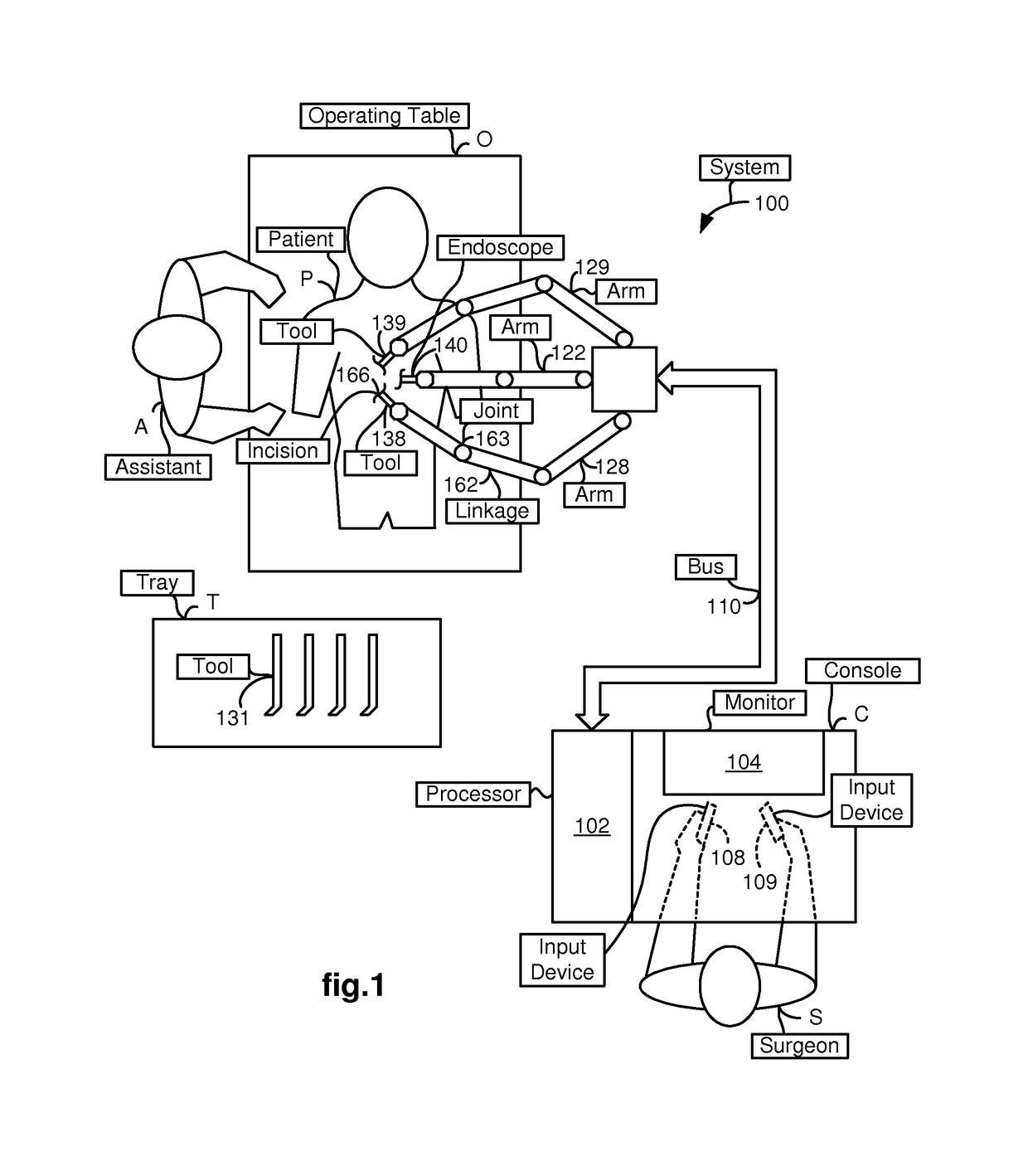
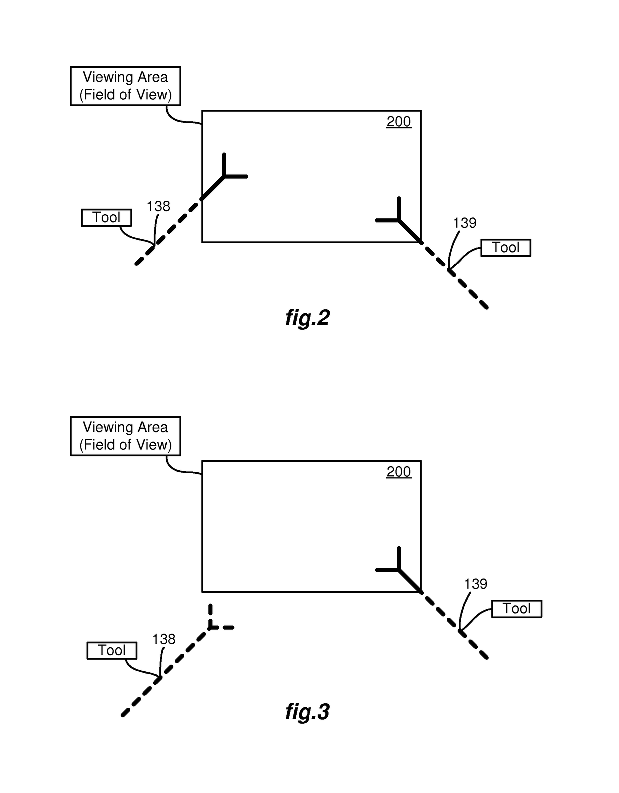
[0027]FIG. 1 illustrates, as an example, a top view of an operating room employing a robotic surgical system. The robotic surgical system in this case is a Minimally Invasive Robotic Surgical (MIRS) system 100 including a Console (“C”) utilized by a Surgeon (“S”) while performing a minimally invasive diagnostic or surgical procedure, usually with assistance from one or more Assistants (“A”), on a Patient (“P”) who is lying down on an Operating table (“O”).

[0028]The Console includes a 3-D monitor 104 for displaying an image of a surgical site to the Surgeon, one or more manipulatable master manipulators 108 and 109 (also referred to herein as “control devices” and “input devices”), and a processor 102. The control devices 108 and 109 may include any one or more of a variety of input devices such as joysticks, gloves, trigger-guns, hand-operated controllers, or the like. The processor 102 is a personal computer that is integrated into the Console or positioned next to it.

[0029]The Sur...


PUM


Abstract

An endoscope captures images of a surgical site for display in a viewing area of a monitor. When a tool is outside the viewing area, a GUI indicates the position of the tool by positioning a symbol in a boundary area around the viewing area so as to indicate the tool position. The distance of the out-of-view tool from the viewing area may be indicated by the size, color, brightness, or blinking or oscillation frequency of the symbol. A distance number may also be displayed on the symbol. The orientation of the shaft or end effector of the tool may be indicated by an orientation indicator superimposed over the symbol, or by the orientation of the symbol itself. When the tool is inside the viewing area, but occluded by an object, the GUI superimposes a ghost tool at its current position and orientation over the occluding object.

Description

FIELD OF THE INVENTION[0001]The present invention generally relates to robotic surgical systems and in particular, to a tool position and identification indicator displayed in a boundary area of a computer display screen.BACKGROUND OF THE INVENTION[0002]Robotic surgical systems such as those used in performing minimally invasive surgical procedures offer many benefits over traditional open surgery techniques, including less pain, shorter hospital stays, quicker return to normal activities, minimal scarring, reduced recovery time, and less injury to tissue. Consequently, demand for minimally invasive surgery using robotic surgical systems is strong and growing.[0003]One example of a robotic surgical system is the da Vinci® Surgical System from Intuitive Surgical, Inc., of Sunnyvale, Calif. The da Vinci® system includes a surgeon's console, a patient-side cart, a high performance 3-D vision system, and Intuitive Surgical's proprietary EndoWrist™ articulating instruments, which are mod...

Claims


Application Information

Patent Timeline
Patent Type & Authority Patents(United States)
IPC IPC(8): A61B17/00B25J9/16A61B34/10A61B34/20A61B90/00A61B1/00G06F3/048G06F3/0481
CPCB25J9/1692A61B90/36A61B1/00009A61B17/00234A61B34/20A61B90/361A61B2017/00199A61B2017/00292A61B2017/00296A61B2034/102A61B2034/107A61B2090/365A61B2090/367A61B2090/371B25J9/1694B25J9/1697G05B2219/39449G05B2219/40607G05B2219/45123A61B1/0051A61B1/0005B25J9/16A61B2034/2057A61B2034/2065A61B34/30A61B2034/301A61B90/37A61B2090/373A61B1/3132A61B34/10A61B34/25A61B34/37A61B34/74A61B2034/741A61B2034/742
Inventor LARKIN, DAVID Q.NIXON, THOMAS ROBERTMINTZ, DAVID STEPHEN
Owner INTUITIVE SURGICAL OPERATIONS INC
Why Eureka
Try Eureka