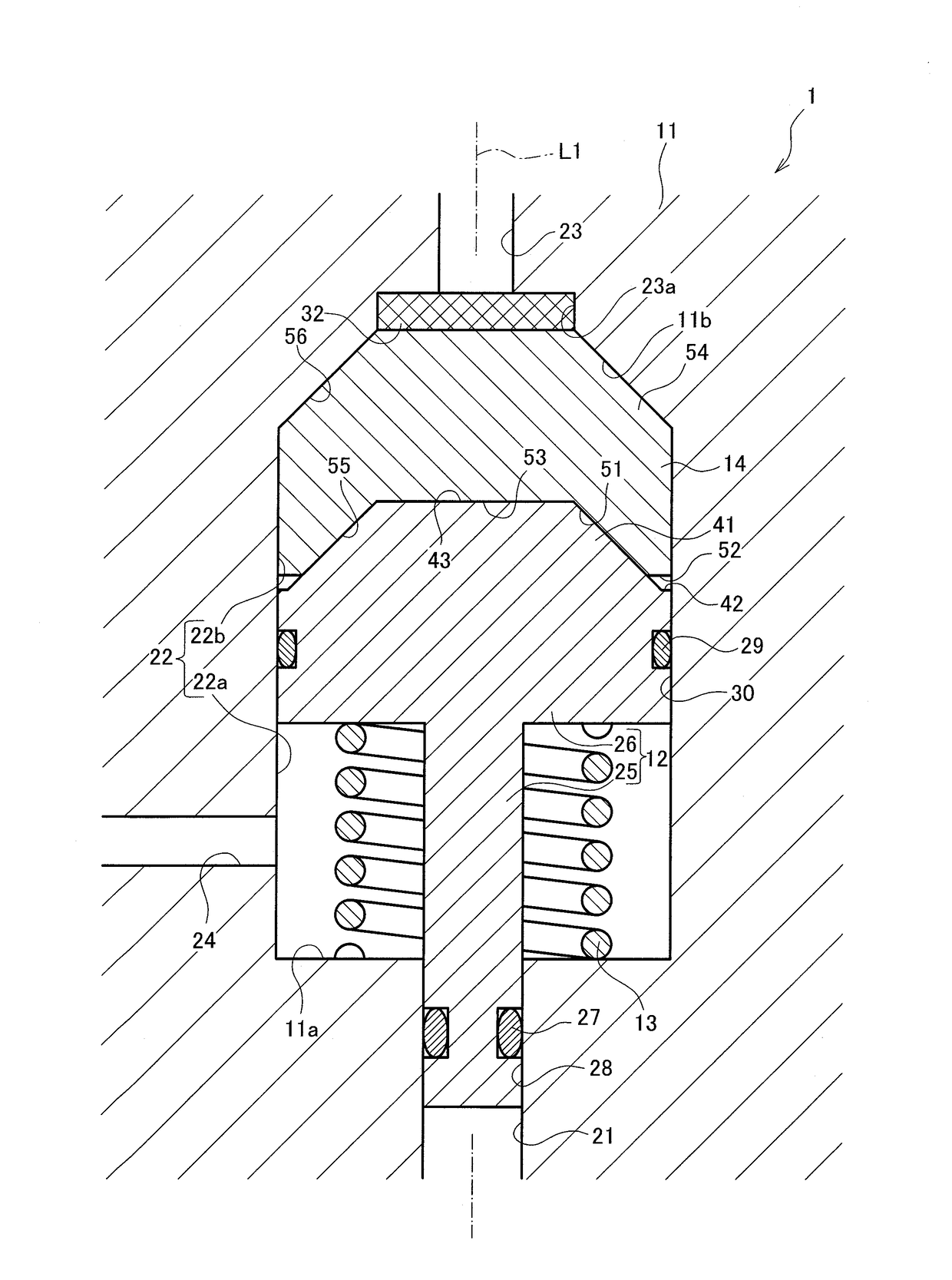
Fusible plug type pressure relief valve
a pressure relief valve and plug-type technology, which is applied in the direction of valve arrangements, venting valves, safety valves, etc., can solve the problems of tank burst, and achieve the effect of suppressing the amount of creep deformation of the supporting body
- Summary
- Abstract
- Description
- Claims
- Application Information
AI Technical Summary
Benefits of technology
Problems solved by technology
Method used
Image
Examples
first embodiment
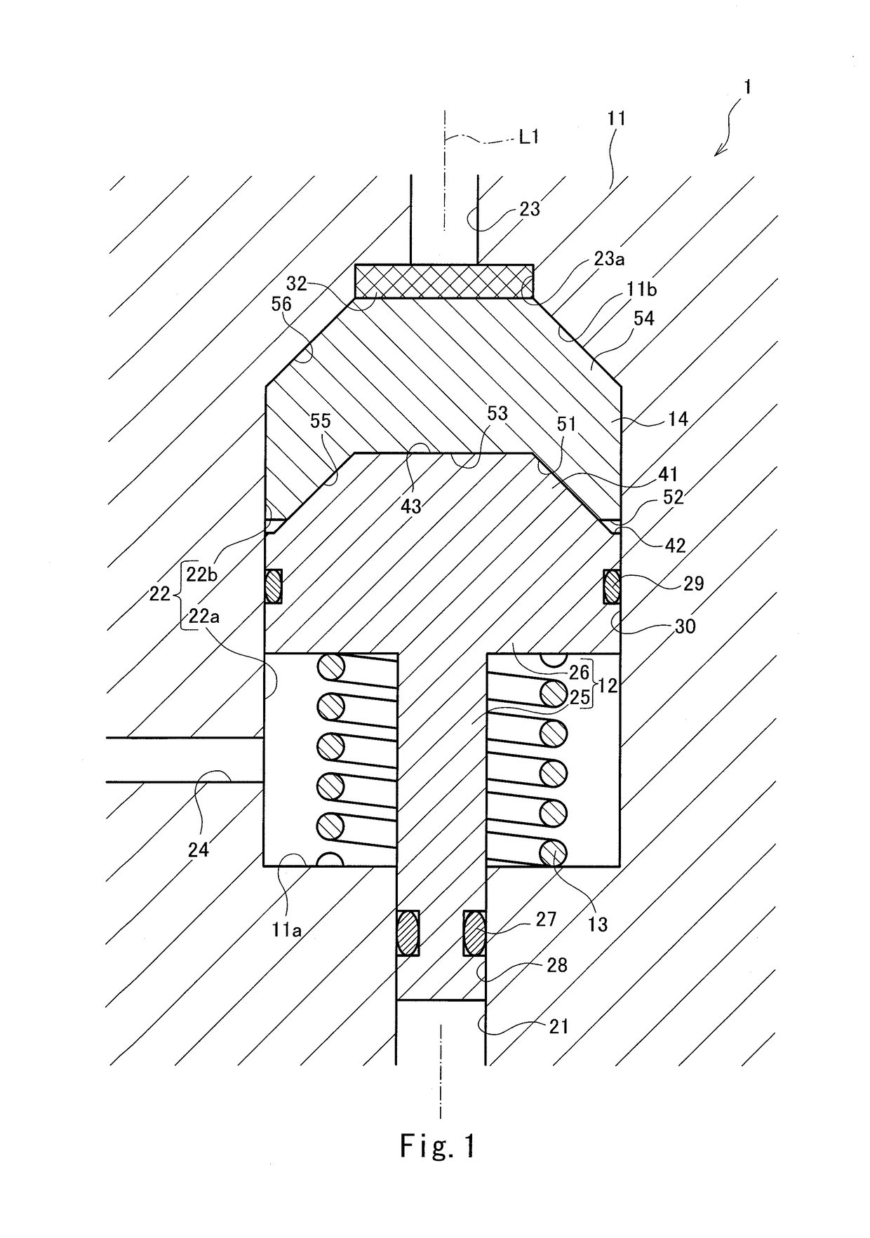
[0036]A gas tank is provided with a fusible plug type pressure relief valve 1. When a temperature around a pressure apparatus increases at the time of fire or the like to become a predetermined temperature, the fusible plug type pressure relief valve 1 releases a gas in the tank to the atmosphere. Hereinafter, the fusible plug type pressure relief valve 1 provided at the tank will be explained in detail.
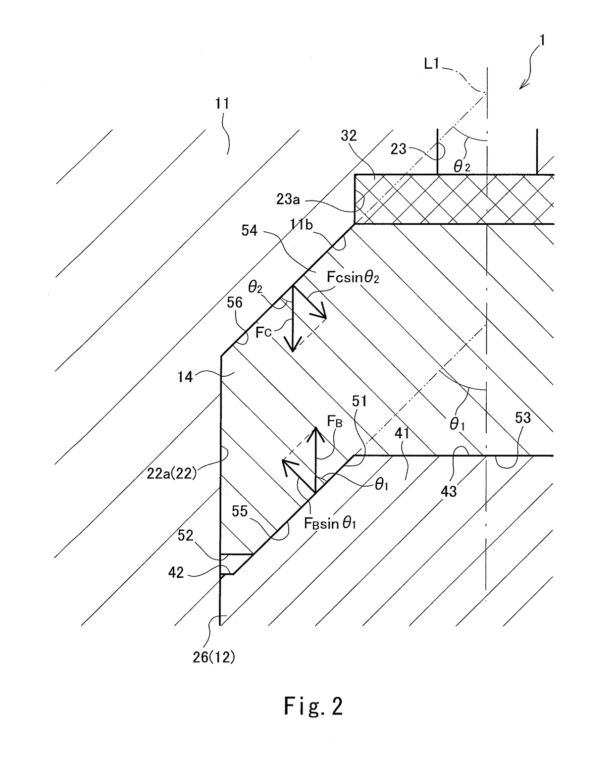
[0037]The fusible plug type pressure relief valve 1 includes a housing 11, a valve element 12, a spring member 13, and a fusible piece 14. The housing 11 includes a valve passage 21, a valve space 22, a discharge passage 23, and an atmosphere communication passage 24. The valve passage 21 is connected to the tank, and the gas in the tank is introduced to the valve passage 21. The valve passage 21 is connected to the valve space 22, and the valve space 22 is larger in diameter than the valve passage 21. The valve space 22 is connected to the discharge passage 23 and the atmosphere com...
second embodiment
[0049]A fusible plug type pressure relief valve 1A of the second embodiment is similar in configuration to the fusible plug type pressure relief valve 1 of the first embodiment. The following will mainly explain components of the fusible plug type pressure relief valve 1A of the second embodiment, the components being different from the components of the fusible plug type pressure relief valve 1 of the first embodiment. The same reference signs are used for the same components, and explanations thereof may be omitted. The same is true for the fusible plug type pressure relief valves 1B to 1E of the third to sixth embodiments and a fusible plug type pressure relief valve 1F of another embodiment.
[0050]As shown in FIG. 3, in the fusible plug type pressure relief valve 1A, an upper end surface 14a of a fusible piece 14A is a flat surface perpendicular to the axis line L1. An outer diameter of the porous member 32 is substantially equal to an outer diameter of the fusible piece 14A. The...
third embodiment
[0052]As shown in FIG. 4, in a fusible plug type pressure relief valve 1B of the third embodiment, a concave portion 41B is formed at an upper end portion of a piston 26B of a valve element 12B. The concave portion 41B has a substantially truncated cone shape that is concave toward the bottom surface 11a of the housing 11 (i.e., toward the closed position). The concave portion 41B is formed along the axis line L1. A lower end portion of the fusible piece 14B forms a convex portion 51B. The convex portion 51B has a substantially truncated cone shape corresponding to the shape of the concave portion 41B of the piston 26B. To be specific, the convex portion 51B has a substantially truncated cone shape projecting toward the bottom surface 11a of the housing 11 (i.e., toward the closed position). The convex portion 51B is formed along the axis line L1. The convex portion 51B having such a shape is fitted in the concave portion 41B such that an outer surface of the convex portion 51B cont...
PUM
 Abstract
Description
Claims
Application Information
 - R&D
- Intellectual Property
- Life Sciences
- Materials
- Tech Scout
- Unparalleled Data Quality
- Higher Quality Content
- 60% Fewer Hallucinations
Browse by: Latest US Patents, China's latest patents, Technical Efficacy Thesaurus, Application Domain, Technology Topic, Popular Technical Reports.
© 2025 PatSnap. All rights reserved.Legal|Privacy policy|Modern Slavery Act Transparency Statement|Sitemap|About US| Contact US: help@patsnap.com


