
Wire harness and method for manufacturing wire harness

a wire harness and wire harness technology, applied in the direction of insulated conductors, rigid-tube cables, cables, etc., can solve the problems of complex bending and branching shape of wire harnesses for automobile use, and achieve the effect of efficient arrangemen

Active Publication Date: 2017-06-06
FURUKAWA ELECTRIC CO LTD +1
View PDF19 Cites 7 Cited by
  • Summary
  • Abstract
  • Description
  • Claims
  • Application Information

AI Technical Summary

Benefits of technology

[0041]The coupling of the connector holding jig is released and divided into the sub-jigs, and the sub-jigs are arranged on the protector mounting table. This enables the connectors to be arranged in positions suitable for mounting of the protectors. Since a plurality of connectors can be handled collectively on the basis of the sub-jigs, the connectors and the electric wires can be efficiently arranged on the protector mounting table.

Problems solved by technology

Recently, an automobile includes various electrical devices mounted in various parts of a vehicle body, and therefore a wire harness for use in an automobile has a complicated bending and branching shape.

Method used


Image

  • Wire harness and method for manufacturing wire harness
  • Wire harness and method for manufacturing wire harness
  • Wire harness and method for manufacturing wire harness

Examples


Embodiment Construction

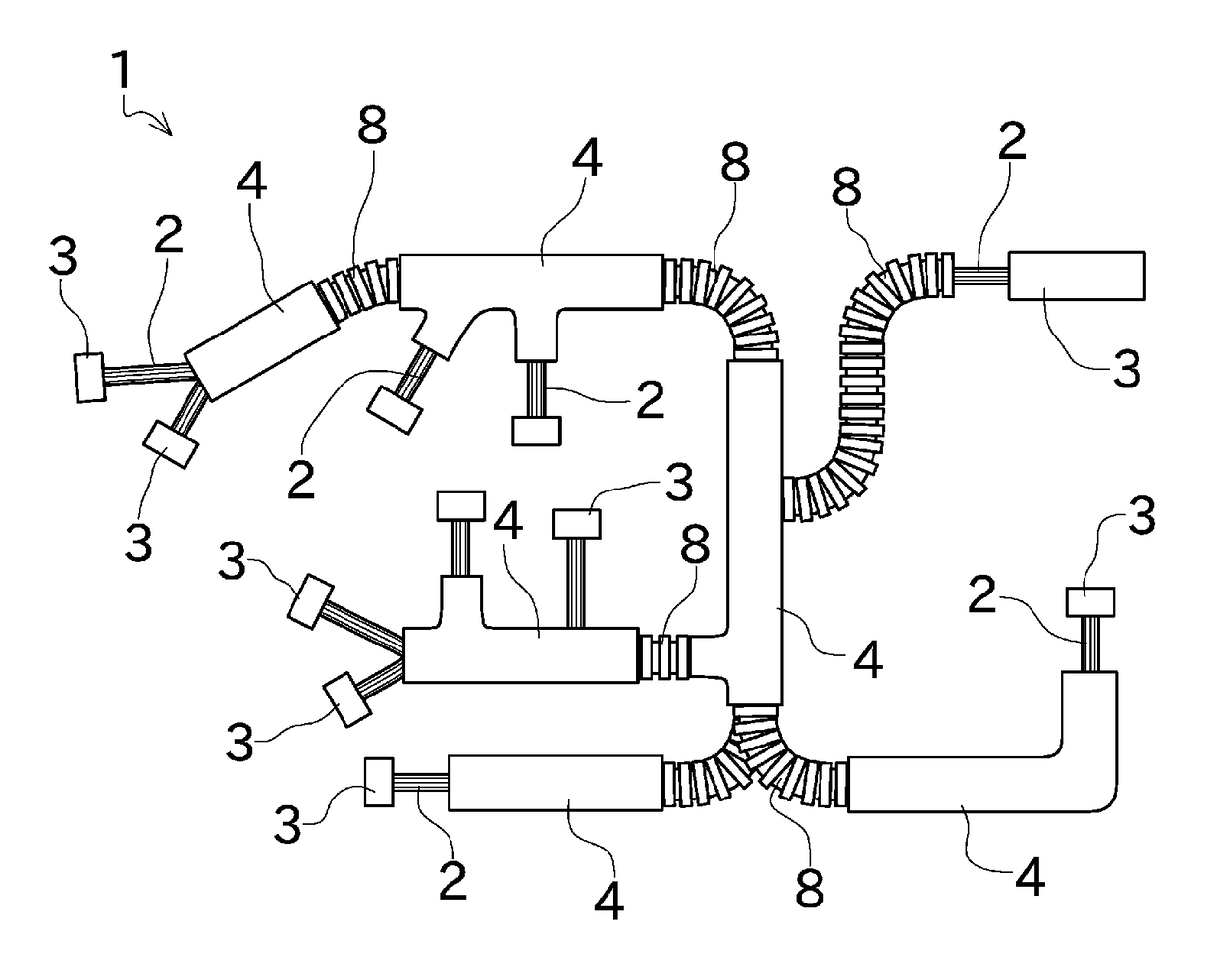
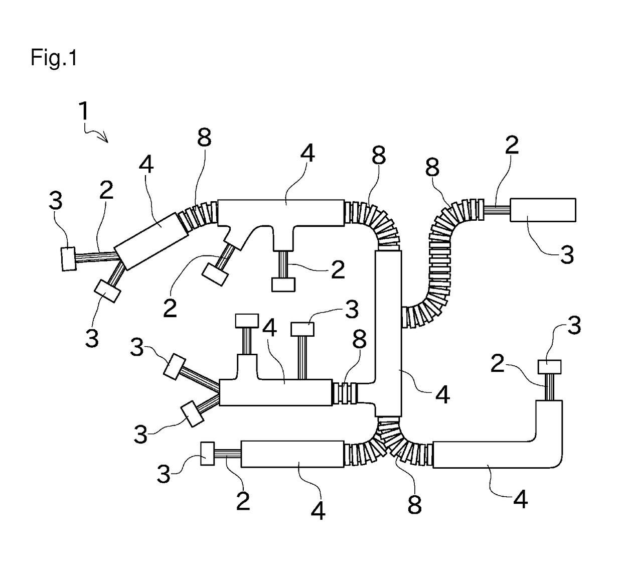
[0068]An embodiment of the present invention will be described with reference to the drawings. FIG. 1 is a plan view showing an outline of an example of a wire harness 1 according to this embodiment. The wire harness 1 of this embodiment is a wire harness for use in an automobile, and wired in a vehicle body of the automobile. The wire harness 1 is used for power supply to various electrical devices provided in the automobile, communication among the electrical devices, and the like.

[0069]The wire harness 1 includes a bundle of a plurality of electric wires 2. Connectors 3 connected to the various electrical devices are arranged at the terminals of the electric wires 2, respectively. Each of the electric wires 2 is wired into a predetermined bending shape. The wire harness 1 as a whole has a complicated branching structure (branching shape).

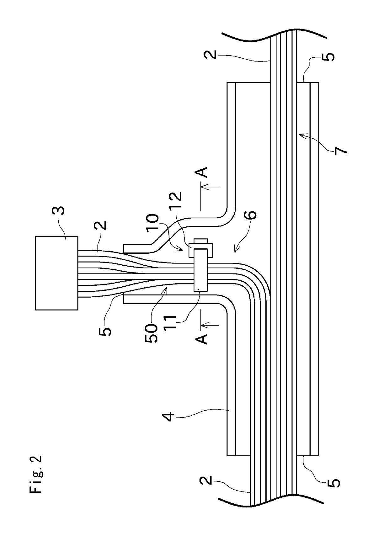
[0070]Protectors 4 are arranged in various portions of the wire harness 1. An exemplary configuration of the protector 4 is shown in FIGS. 2 to ...


PUM

PropertyMeasurementUnit
shapeaaaaaaaaaa
dimensionaaaaaaaaaa
sizeaaaaaaaaaa

Abstract

The invention of the present application provides a wire harness with an improved accuracy of the dimension, that can be manufactured with an easy operation. A protector (4) defines at least either one of a bending shape and a branching shape of a plurality of electric wires (2). A cable tie (10) is attached to the electric wires (2), and includes a distal portion (11a) to be attached to the protector (4). The protector (4) includes an engaging portion (13) engageable with the distal portion (11a). Positions of the electric wires (2) and the protector (4) relative to each other are settled by engagement of the distal portion (11a) of the cable tie (10) attached to the electric wires (2) with the engaging portion (13).

Description

CROSS-REFERENCE TO RELATED APPLICATIONS[0001]This application is a U.S. National Stage application filing under 35 USC §371 of International Application No. PCT / JP2013 / 006407, filed on Oct. 29, 2013, entitled “WIRE HARNESS AND METHOD FOR MANUFACTURING WIRE HARNESS,” which claims priority to Japanese Application No. 2012-238266, filed on Oct. 29, 2012, and which also claims priority to Japanese Application No. 2012-238267, filed on Oct. 29, 2012, the entireties of each of which are incorporated herein by reference.TECHNICAL FIELD[0002]The present invention relates to a configuration of a wire harness and a method for manufacturing the wire harness.BACKGROUND ART[0003]A wire harness includes a bundle of a plurality of electric wires formed into a predetermined shape. The wire harness is, for example, wired in a vehicle body of an automobile, and used for power supply to various electrical devices provided in the automobile, communication of control signals among the electrical devices...

Claims


Application Information

Patent Timeline
Patent Type & Authority Patents(United States)
IPC IPC(8): H02G3/04H01B7/16B60R16/02H01B13/004H01B13/012H01B7/00
CPCH01B13/01209B60R16/0207H01B7/0045H01B7/16H01B13/004H01B13/012
Inventor SAKAKI, NAOYATOMINAGA, MICHIHIKO
Owner FURUKAWA ELECTRIC CO LTD
Learn More