
Method for detecting a device that generates spurious signals in an electrical network, an electrical system and an aircraft

a technology of spurious signals and electrical networks, applied in the direction of instruments, voting arrangements, measurement using digital techniques, etc., can solve problems such as behavior, and achieve the effect of reducing or eliminating power consumption, reducing or completely power consumption, and reducing power consumption

Active Publication Date: 2017-06-06
AIRBUS OPERATIONS GMBH
View PDF16 Cites 0 Cited by
  • Summary
  • Abstract
  • Description
  • Claims
  • Application Information

AI Technical Summary

Benefits of technology

[0018]The method according to an aspect of the invention makes error detection clearly more reliable and simpler, so that unequivocal diagnoses may be arrived at with respect to the correct function of the devices arranged in the electrical network. In addition, it is possible to reduce the weight and manufacturing costs of the electrical network or overall system comprised of the electrical network and electrical devices hooked up thereto, since it is no longer necessary to have each device incorporate corresponding sensors to monitor the respective device for electrical errors. An individual fault detection device in the network may preferably monitor several, many or all electrical devices, so that the majority of devices no longer have to perform any internal error monitoring. A fault detection device integrated into an electrical device may further be prevented from interpreting an electrical error released into the electrical network by another device as an intrinsic electrical error and issuing a false report. However, the fault detection device itself may also be situated in one of the devices connected with the network.
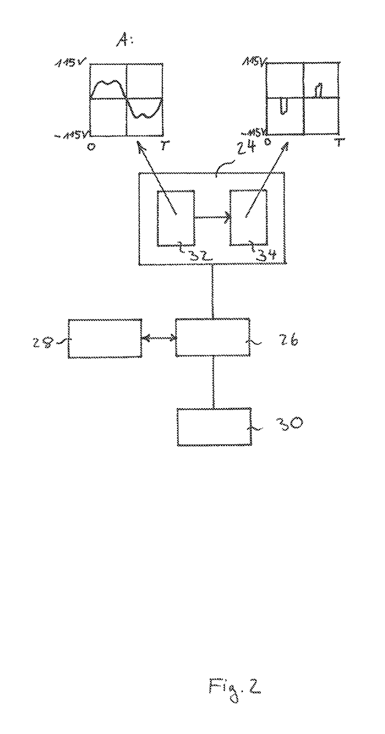
[0034]In an advantageous embodiment, the at least one fault detection device comprises a recorder for recording the progression of an electrical variable, along with at least one electronic unit configured to filter known frequency patterns out of the recorded progression. As already described above, this makes it possible to analyze an electrical spurious signal distributed over the electrical network.

Problems solved by technology

A substantial influence is exerted by circuit feedback, which results from an arising error in an electrical component of a device connected with the electrical network.
In particular, such a behavior may arise in the case of defects in power electronics, for example comprising bipolar transistors, thyristors or the like, semiconductors in general, mechanical defects in electrical lines or other electrical errors.

Method used


Image

  • Method for detecting a device that generates spurious signals in an electrical network, an electrical system and an aircraft
  • Method for detecting a device that generates spurious signals in an electrical network, an electrical system and an aircraft
  • Method for detecting a device that generates spurious signals in an electrical network, an electrical system and an aircraft

Examples


Embodiment Construction

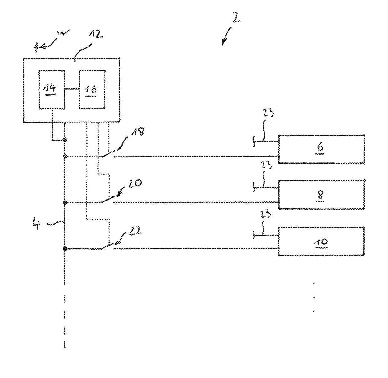
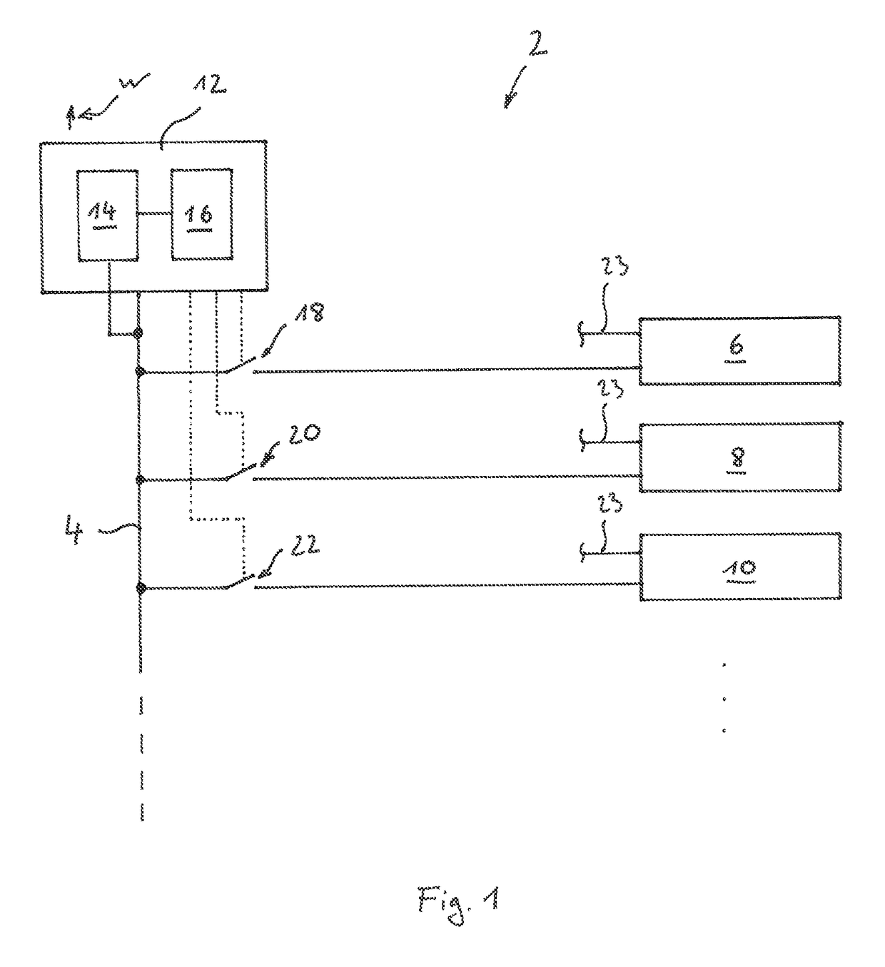
[0039]FIG. 1 shows an electrical system 2 with an electrical network 4 to which several devices 6, 8 and 10 are connected. Also connected to the electrical network 4 is a fault detection device, which may comprise at least one recorder 14 and one electronic unit 16, which is hooked up with the recorder 14. The recorder 14 is able to record the progression of an electrical variable on the electrical network 4, and make it available internally as a signal that may be further processed. The electrical variable may here be a voltage or a current.

[0040]For example, the electronic unit 16 may be a calculator unit or consist of simpler digital and / or analog circuits. The electronic unit is primarily configured to filter known frequency patterns out of the recorded progression of the electrical variable, for example those belonging to the injected alternating voltage. If the electrical system 2 is located in an aircraft, for example, an alternating voltage with a frequency of 400 Hz and an ...


PUM


Abstract

A method for detecting a device that generates spurious signals in an electrical network, to which several devices and at least one fault detection device are connected, includes the steps of monitoring the electrical network for electrical spurious signals, sequentially deactivating each device for a predetermined time T when an electrical spurious signal has been detected, and checking the electrical network for the disappearance of the respective spurious signal, and signaling as soon as the respective spurious signal has disappeared upon deactivating a respective device. This makes it possible to especially reliably detect a device in an electrical network that couples an undesired spurious signal into the network.

Description

CROSS-REFERENCE TO RELATED APPLICATIONS[0001]The present application claims the benefit of the filing date of U.S. Provisional Patent Application No. 61 / 705,928, filed Sep. 26, 2012, the disclosure of which is hereby incorporated herein by reference.TECHNICAL AREA[0002]The invention relates to a method for detecting a device that generates spurious signals in an electrical network, an electrical system as well as an aircraft with such an electrical system.BACKGROUND OF THE INVENTION[0003]Electrical devices and equipment in buildings or vehicles are usually supplied via an electrical network over which the electrical power is distributed. The latter is here provided by one or more power supply units and transmitted over electrical lines. Due to the combined use of electrical lines within such a network, electrical spurious signals released by individual devices via their connection to the electrical network can be detected by other devices.[0004]Electrical consumers in vehicles and i...

Claims


Application Information

Patent Timeline
Patent Type & Authority Patents(United States)
IPC IPC(8): G01R31/00G01R31/28G01R19/25B60L1/00G01R1/00
CPCG01R31/2836G01R19/2513G01R31/008B60L1/00G01R1/00G06Q2230/00
Inventor EVERTH, HENNINGSCHULT, JENS
Owner AIRBUS OPERATIONS GMBH
Learn More