
Method of stapling tissues with a staple assembly

a tissue and staple technology, applied in surgical staples, manufacturing tools, veterinary instruments, etc., can solve the problems of tissue pulling apart, leakage between tissues, and only being able to effectively seal together a limited range of thicknesses of staples

Inactive Publication Date: 2017-05-02
TYCO HEALTHCARE GRP LP
View PDF196 Cites 626 Cited by
  • Summary
  • Abstract
  • Description
  • Claims
  • Application Information

AI Technical Summary

Benefits of technology

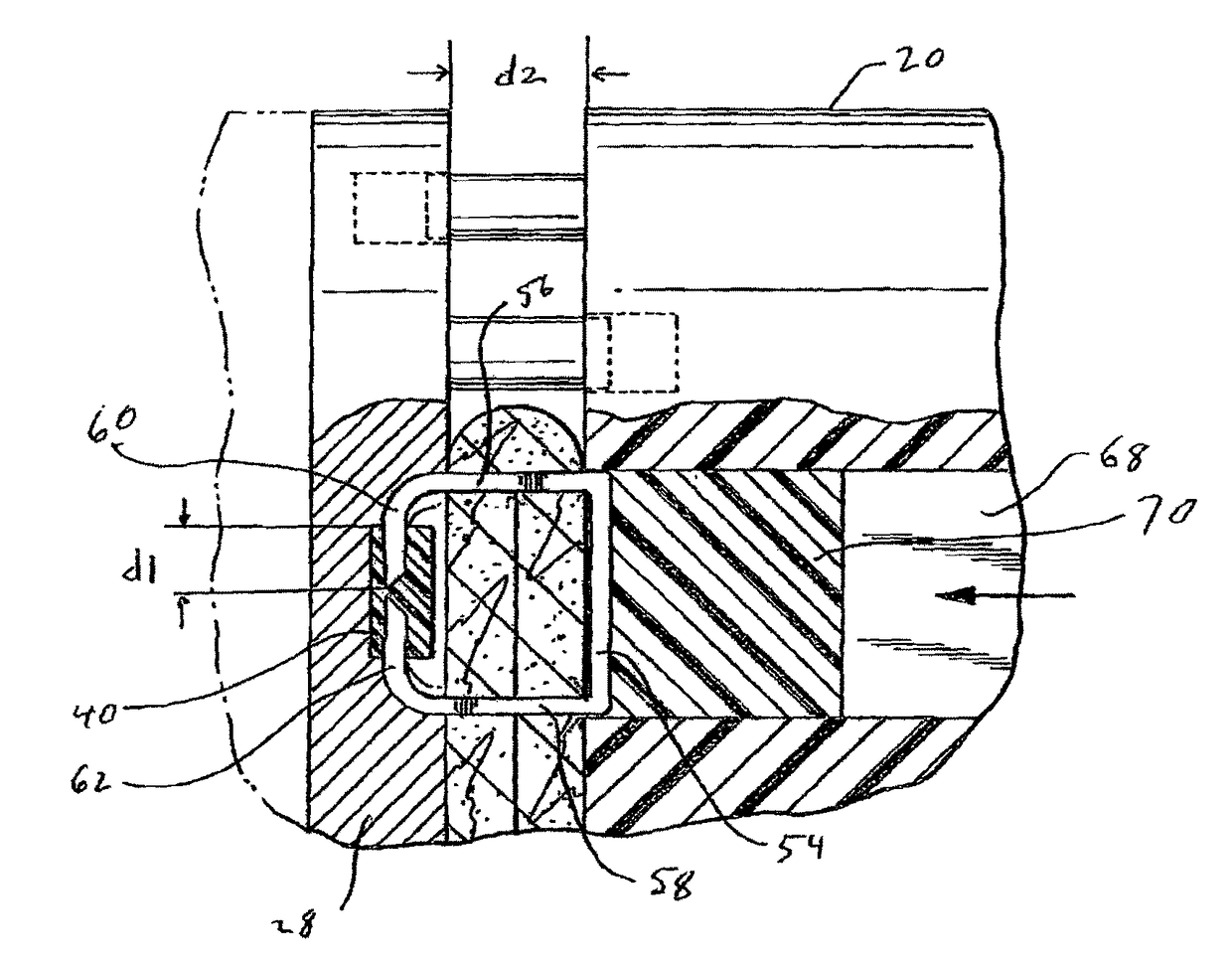
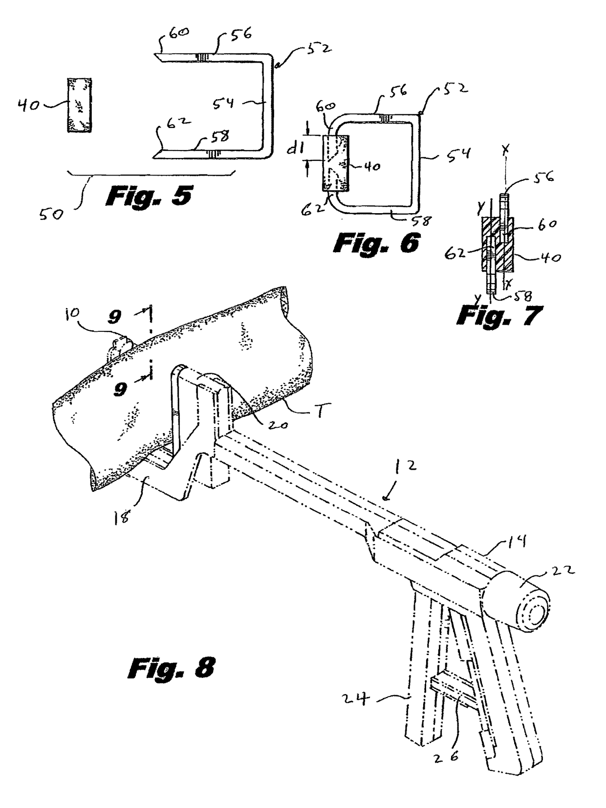
The patent describes a staple assembly for use with various thicknesses of tissues. The staple has a backspan and two legs that penetrate the tissue. The assembly also includes a staple block that can receive the tissue penetrating tips of the staple. The staple and staple block work together so that the tips of the staple lodge into the staple block to a depth proportional to the thickness of the tissue. The staple block can be made of a composite material or various other materials such as plastic or absorbable materials. The staple assembly can be used with a surgical stapler and an anvil. The method involves capturing a tissue between the staple head and anvil and passing the staple through the tissue to secure it. The tips of the staple can pass into the staple block along parallel or common axes. The technical effect of this invention is a staple assembly that allows for secure and uniform stapling of tissues of varying thicknesses.

Problems solved by technology

However, the chosen staple is only capable of effectively sealing together a limited range of thicknesses of tissues.
If the tissues are too thick for the chosen staple, the surgical stapler may not fully crimp the staple about the tissue resulting in the tissues pulling apart.
Conversely, if the tissues are too thin for the chosen staple, the crimped or formed staple may not have enough compression to fully seal the tissues together resulting in leakage between the tissues.
In other situations where the tissues are too thin for the chosen staple, the staple may be over crimped causing tissue penetrating tips of the staple to recurve back upon itself resulting in unnecessary puncturing of the tissues and again the possibility of leakage between the tissues.

Method used


Image

  • Method of stapling tissues with a staple assembly
  • Method of stapling tissues with a staple assembly
  • Method of stapling tissues with a staple assembly

Examples


Embodiment Construction

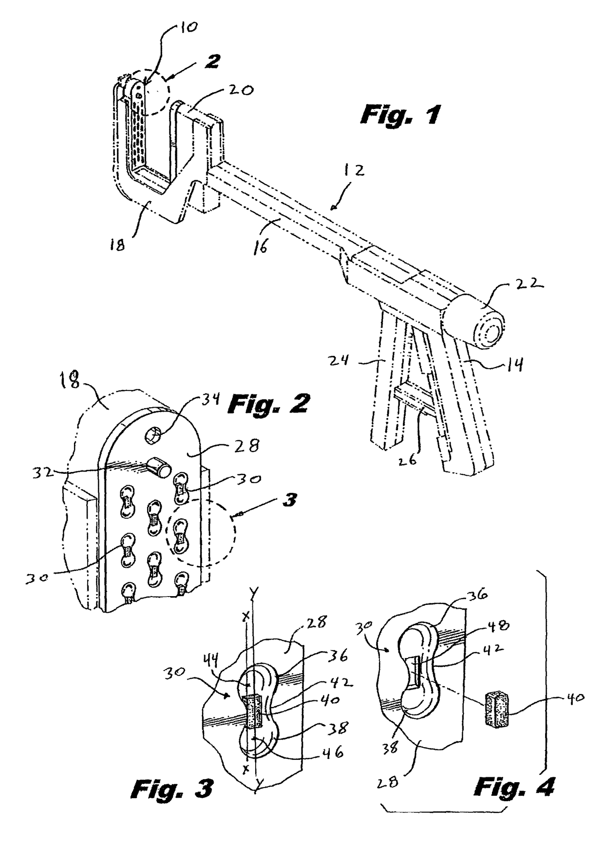
[0030]Embodiments of the presently disclosed variable size, uniform compression staple assembly and associated anvil will now be described in detail with reference to the drawings wherein like numerals designate identical or corresponding elements in each of the several views. As is common in the art, the term “proximal” refers to that part or component closer to the user or operator, i.e. surgeon or physician, while the term “distal” refers to that part or component further away from the user.

[0031]Referring initially to FIG. 1, there is disclosed an anvil 10 for use with a surgical stapler 12. Surgical stapler 12 is of a type typically used for open surgery procedures and includes a pistol grip handle 14 having an elongate member 16 extending distally from handle 14. Elongate member 16 terminates in a generally U-shaped anvil support 18. Anvil 10 is mounted on anvil support 18. Surgical stapler 12 also includes a staple containing head or staple head 20 which contains a plurality ...


PUM

PropertyMeasurementUnit
thicknessesaaaaaaaaaa
sizeaaaaaaaaaa
lengthaaaaaaaaaa

Abstract

There is provided a variable size, uniform compression staple assembly for use in stapling differing thicknesses of tissues. The staple assembly includes a staple and a staple block for receipt of tissue penetrating tips of the staple. Upon assembly through tissue, the tissue penetrating tips of the staple lodge within the staple block to a depth inversely proportional to the thickness of the tissues being stapled. There is also disclosed an anvil configured for use with the staple assembly.

Description

CROSS REFERENCE TO RELATED APPLICATIONS[0001]This application is a National Stage Application of PCT / US2008 / 062635 filed May 5, 2008 under 35 USC §371(a), which claims priority of U.S. Provisional Application Ser. No. 60 / 928,244 filed on May 7, 2007, the entire contents of which are incorporated herein by reference.BACKGROUND[0002]Technical Field[0003]The present disclosure relates to a variable size, uniform compression staple assembly and an associated anvil for use with a surgical stapling device. More particularly, the present disclosure relates to a two part, variable size, and uniform compression staple assembly for use with various thickness of tissue and an associated anvil for forming the staple assembly about the tissue.[0004]Background of Related Art[0005]Surgical stapling instruments or surgical staplers are used in many surgical operations to secure or join two or more tissue sections together. Some known surgical staplers are preloaded with a pre-chosen specific size s...

Claims


Application Information

Patent Timeline
Patent Type & Authority Patents(United States)
IPC IPC(8): A61B17/068A61B17/064A61B17/072
CPCA61B17/0643A61B17/0686A61B17/0644A61B17/07292A61B2017/07242A61B2017/07264
Inventor WENCHELL, THOMAS
Owner TYCO HEALTHCARE GRP LP
Learn More