Orthopedic clavicle brace

a clavicle brace and orthopaedic technology, applied in the field of orthopaedic clavicle brace, can solve the problems of substantial practical disadvantage for users, user's inability to adjust the tightness or looseness of the shoulder strap, and users of prior art shoulder braces, etc., to achieve easy adjustment, easy application and removal, and promote healing and support

Inactive Publication Date: 2017-04-11
SEARS JACK T
View PDF21 Cites 3 Cited by
  • Summary
  • Abstract
  • Description
  • Claims
  • Application Information

AI Technical Summary

Benefits of technology

[0005]The present invention is directed towards overcoming the problems and disadvantages in previous figure-8 clavicle braces. An object of the present invention is to provide an orthopedic clavicle brace that pulls at the correct angle to the injured clavicle to promote healing and support while allowing easy accessibility to the user for making self-adjustments without having to rely on assistance by a second party. It is still a further object of the invention to provide a clavicle brace which may be easily adjusted for various sizes and shapes of persons and which may be easily applied and removed.
[0006]A preferred embodiment of the present invention discloses a universal clavicle brace for positioning over the upper back of the user including a triangular shaped clavicle brace support body comprising three adjustable fasteners at each corner of the body. A T-shaped shoulder strap with three ends is coupled to an adjustable fastener on the top corner portion of the body by a first end of the shoulder strap. A second end of the shoulder strap extends over a first shoulder of the user. A third end of the shoulder strap extends over a second shoulder of the user. Each second and third end of the shoulder strap includes an adjustable fastener secured thereon opposite the first end attached to the body. A first axilla strap is coupled to an adjustable fastener on the bottom corner portion of the body by one end of the axilla strap. The first axilla strap has a distal end for extending under one axilla of the user, and is coupled to the adjustable fastener secured to the second end of the shoulder strap. A second axilla strap is coupled to an adjustable fastener on the opposite lower corner portion of the body adjacent the first axilla strap. The second axilla strap has a distal end for extending under the second axilla of the user, and is coupled to the adjustable fastener secured to the third end of the shoulder strap. The adjustable fasteners allow for adjustment and tightening of the straps, in addition to application and removal of the brace. The location of the adjustable fasteners towards the front of the user allows for easy accessibility by the user for making self-adjustments, self-application and self-removal of the brace without having to rely on assistance by a second party.

Problems solved by technology

The location of adjustable fasteners in the middle of a user's back when a figure-8 type shoulder brace is being worn results in a significant practical disadvantage to the user.
In other words, the user himself / herself cannot initially set the length of the shoulder straps in a final desired or required position while wearing the prior art figure-8 type shoulder braces, and the user himself / herself cannot adjust the tightness or looseness of the shoulder straps on that type brace as the brace becomes tighter or looser while being worn during everyday life.
Obviously this is a disadvantage of substantial significance to users of prior art shoulder braces when no second person is around to help with desired shoulder strap adjustments.
In other words, these types of figure-8 type braces cannot be adjusted by the user while the shoulder brace is being worn.

Method used


Image

  • Orthopedic clavicle brace
  • Orthopedic clavicle brace
  • Orthopedic clavicle brace

Examples


Embodiment Construction

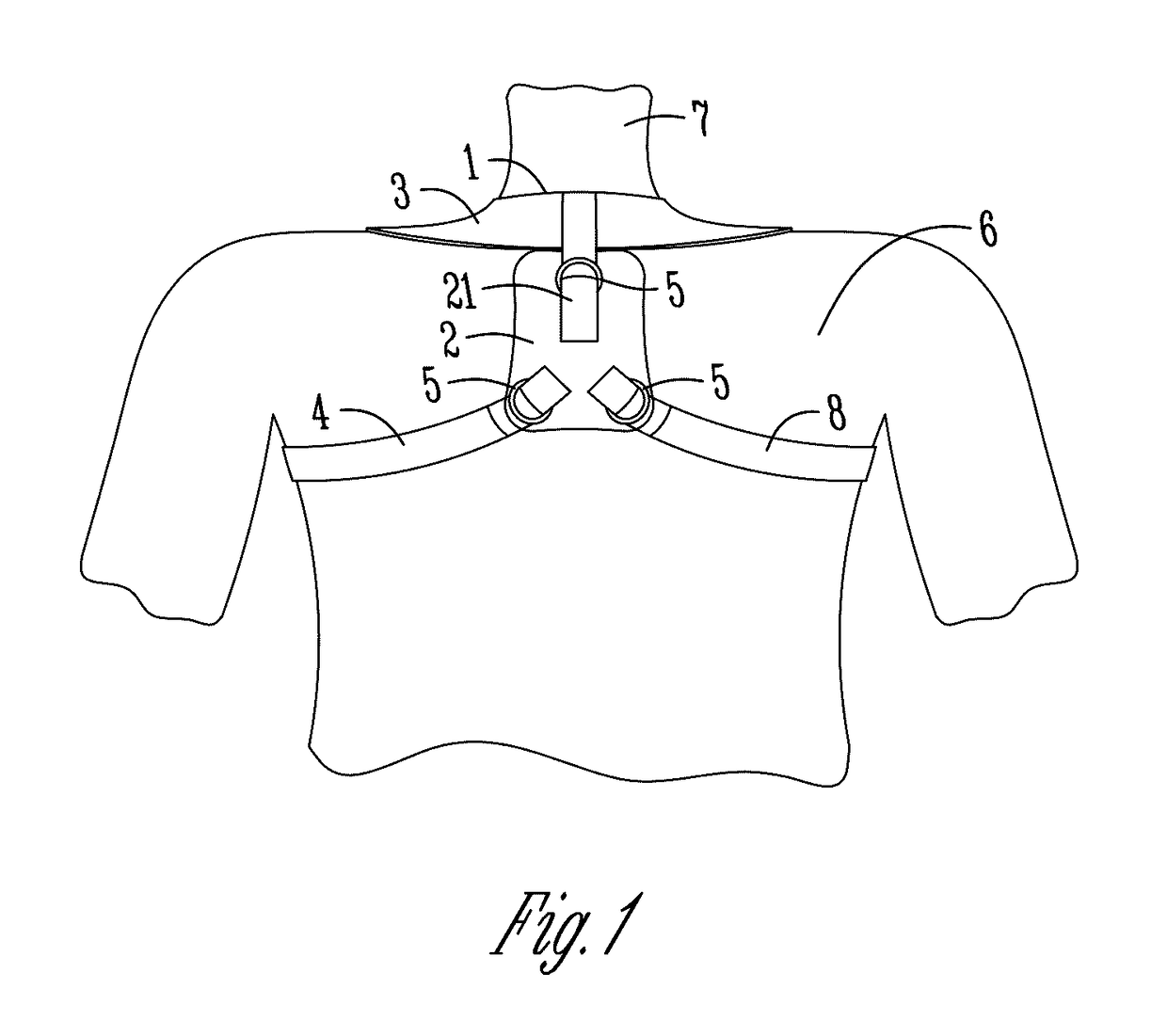
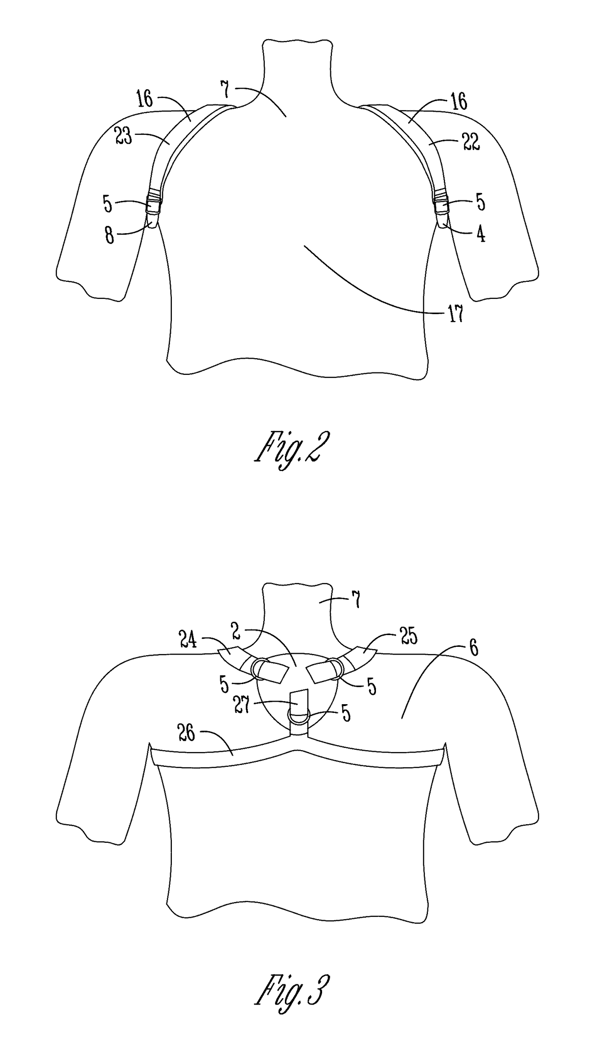
[0017]The orthopedic clavicle brace (1) of the present invention and method for use is for giving support to a user's shoulders to prevent injury and to promote healing of a dislocated, injured or fractured clavicle. A preferred embodiment of the brace (1) includes: a clavicle brace support body (2); a shoulder strap (3); a first axilla strap (4); a second axilla strap (8); and, adjustable fasteners (5). See FIG. 1. The clavicle brace support body (2) is configured to position substantially over the upper back (6) of the user (7). The shoulder strap (3), T-shaped and having three end portions (21, 22, 23), is attached to the upper portion of the body (2) by a proximal first end portion (21) of the strap (3). Portions of the shoulder strap (3) extending around the neck and over the shoulders of the user (7) are typically wider than the first end portion (21) of the shoulder strap (3) coupled to the body (2). This extra width provides additional support to the injured clavicle and nec...


PUM


Abstract

An easily-accessible, self-adjustable orthopedic clavicle brace and method of use for preventing and treating damage to the clavicle. The brace supports the shoulder region of a user's body during the healing or mending of an injured, dislocated, fractured or broken clavicle. The device uses a simple coupling means located towards the front of the user to allow for easy accessibility by the user for self-application, self-adjustment, and self-removal of the brace without having to rely on assistance by a second party.

Description

FIELD OF THE INVENTION[0001]The present invention relates to an easily-accessible, self-adjustable orthopedic clavicle brace and method of use for preventing and treating damage to the clavicle. Such a device would support the shoulder region of a user's body during the healing or mending of an injured, dislocated, fractured or broken clavicle. The purpose of the device is to stretch the clavicle longitudinally and immobilize it such that the surfaces of the fracture will fit and grow together rather than grind against one another. The device uses a simple coupling means located towards the front of the user to allow for easy accessibility by the user for self-application, self-adjustment, and self-removal of the brace without having to rely on assistance by a second party.BACKGROUND OF THE INVENTION[0002]The function of the clavicle bones in the human body is to serve as a strut between the scapula and the sternum. Clavicle bones are joined by one end to the sternum and are joined ...

Claims


Application Information

Patent Timeline
Patent Type & Authority Patents(United States)
IPC IPC(8): A61F5/058A61F5/02
CPCA61F5/026A61F5/05808
Inventor SEARS, JACK T.
Owner SEARS JACK T
Why Eureka
Try Eureka