Pliers for crimping electrical terminals

a technology for crimping electrical terminals and pliers, which is applied in the field of pliers, can solve the problems of tiresome work and achieve the effect of convenient and quick attachment and removal

Active Publication Date: 2017-01-10
LI YU HSIN
View PDF5 Cites 1 Cited by
  • Summary
  • Abstract
  • Description
  • Claims
  • Application Information

AI Technical Summary

Benefits of technology

[0005]Accordingly, it is an object of the present invention to provide improved pliers with interchangeable working jaws which can be easily and quickly attached and detached from the rest of the pliers.

Problems solved by technology

As can be imagined, it is a really tiresome piece of work simply to interchange the pair of working jaws with another pair.

Method used


Image

  • Pliers for crimping electrical terminals
  • Pliers for crimping electrical terminals
  • Pliers for crimping electrical terminals

Examples


Embodiment Construction

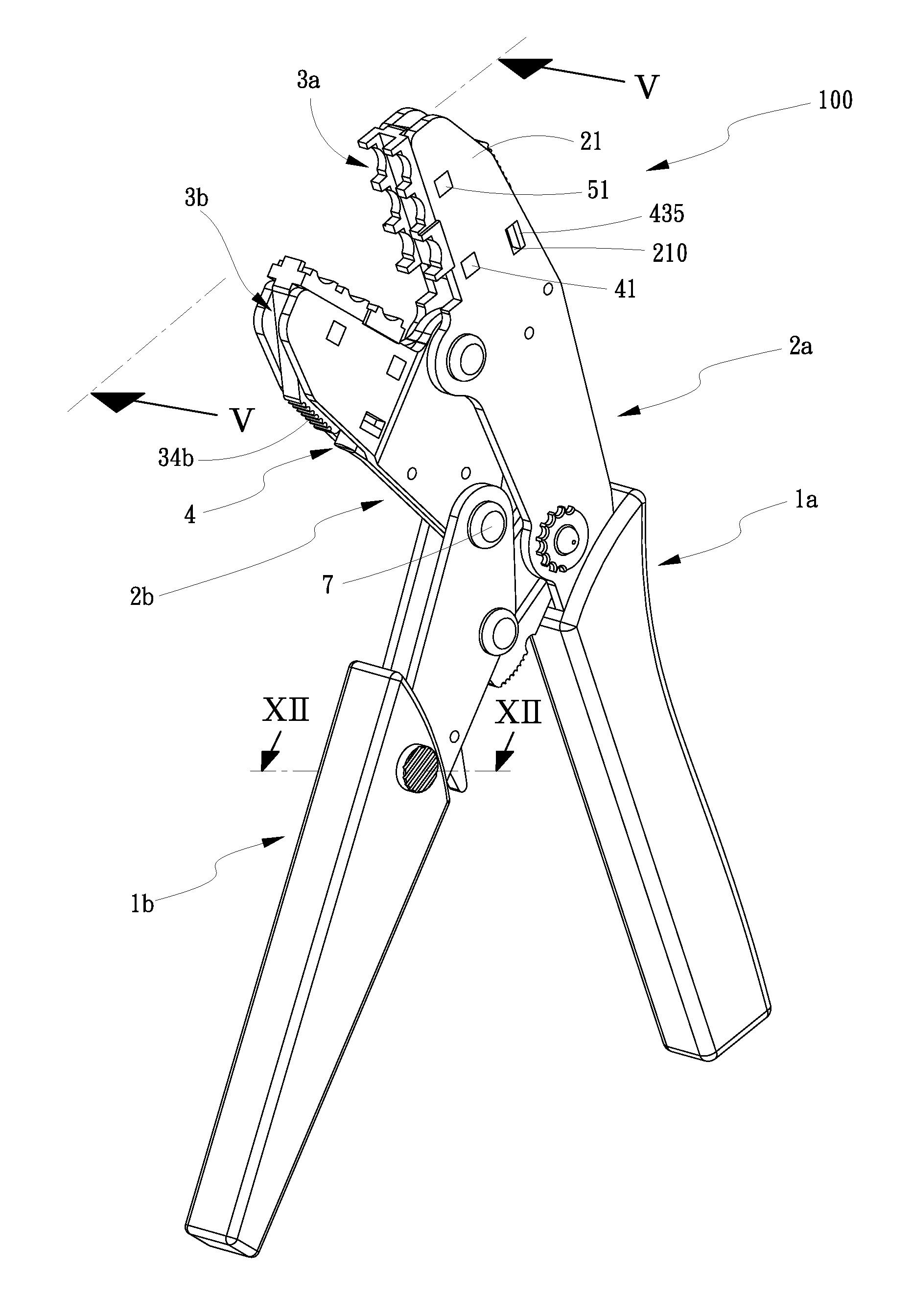
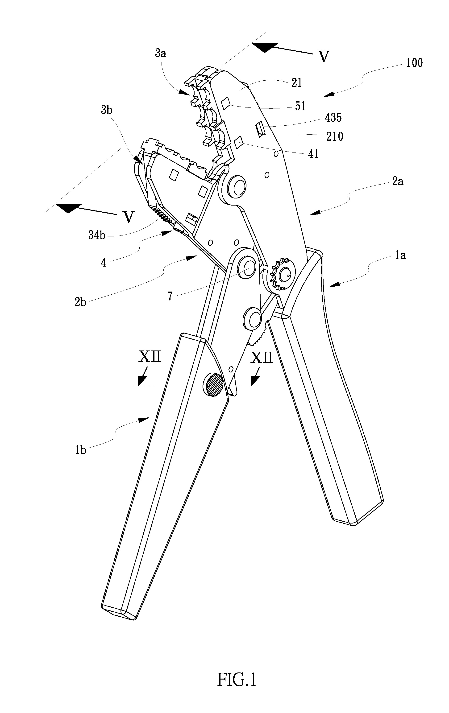
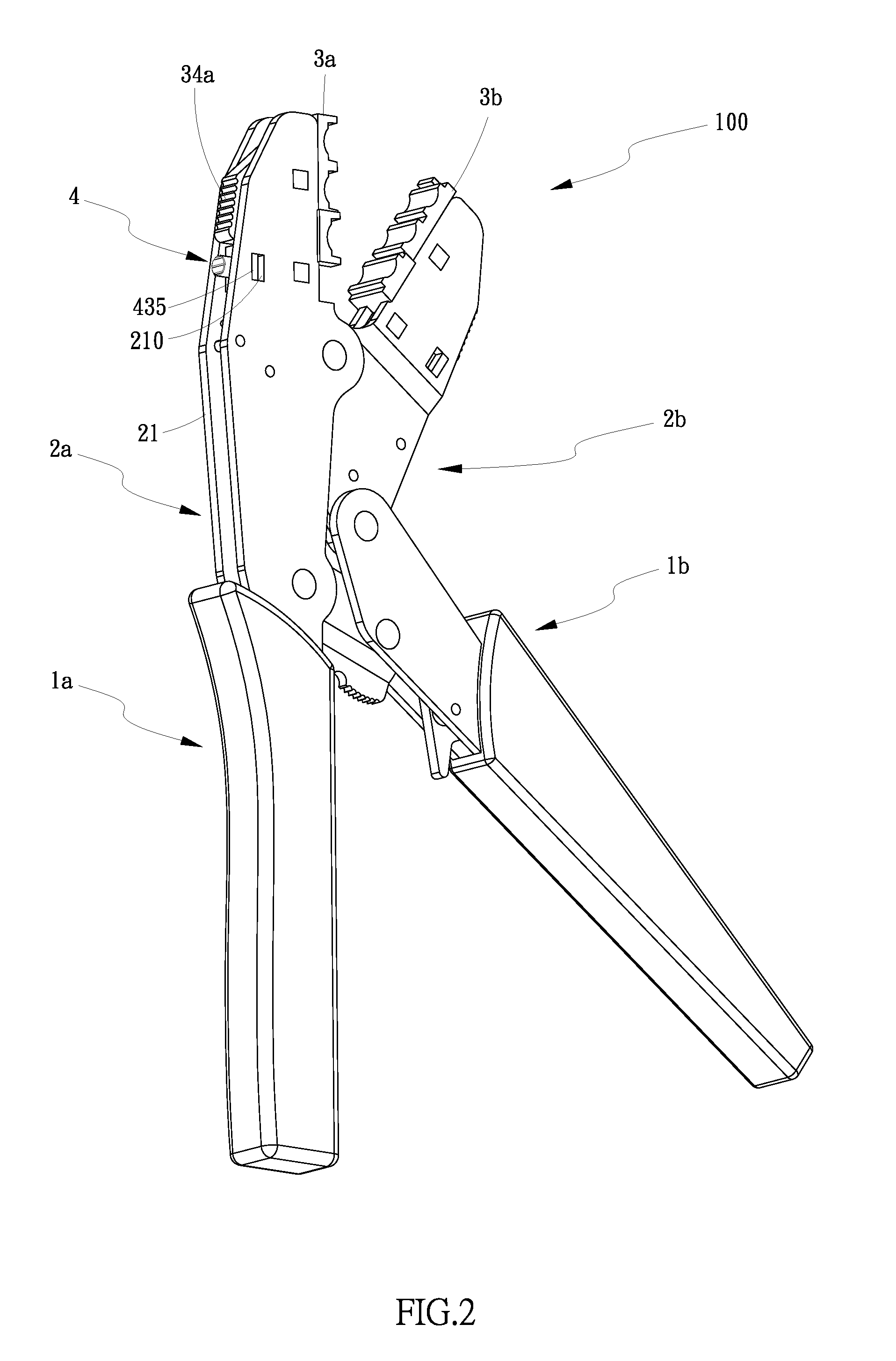
[0028]With reference to FIGS. 1-13, there are shown pliers 100 for crimping terminals on wires or connectors according to a first embodiment of the invention. As shown, the pliers 100 include a pair of handles 1a, 1b, a pair of arm members 2a, 2b and a pair of working jaws 3a, 3b. The right-hand arm member 2a is rigidly connected to or integrated with the right handle 1a. The left-hand arm member 2b is pivotally connected to the left-hand handle 1b by means of a pivot pin 7. The handles 1a, 1b are pivotally connected for movement of the arm members 2a, 2b towards and away from each other. The working jaws 3a, 3b can be interchanged with other pairs of jaws 3a′, 3b′ (see FIG. 19) and they are fixed to their associated arm members 2a, 2b in a manner which will be described later in further detail. As shown in FIGS. 1 and 2, it is preferred that each of the working jaws 3a, 3b have a textured side surface 34a or 34b to facilitate gripping of the working jaw 3a or 3b for further interch...


PUM

PropertyMeasurementUnit
distanceaaaaaaaaaa
sizesaaaaaaaaaa
movementaaaaaaaaaa

Abstract

Pliers include a pair of arm members, a pair of handles, at least one interchangeable working jaw and a control mechanism. Each arm member includes two parallel arm plates. The handles are connected to each other for movement of the arm members towards and away from each other. The working jaw is detachably supported in between the arm plates of the associated arm member. The control mechanism includes a retaining spacer, a driving member and a spring biased between the retaining spacer and the driving member. The retaining spacer is positioned in between the arm plates of the arm member. The driving member is movably disposed in between the arm plates of the arm member and has an end knob exposed outside the arm member so that pressing of the end knob of the driving member drives the driving member to be engaged with or disengaged from the working jaw.

Description

BACKGROUND OF THE INVENTION[0001]1. Field of the Invention[0002]The present invention relates to pliers and more particularly to pliers for crimping electrical terminals with interchangeable working jaws.[0003]2. Description of the Related Art[0004]As disclosed in U.S. Pat. No. 4,381,661, conventional crimping pliers often provide a pair of working jaws attached to two arm members of the crimping pliers by screws. Thus, the working jaws with different sizes or shapes may be removed by loosening the screws and replaced by new ones and finally re-tightening the screws back again. As can be imagined, it is a really tiresome piece of work simply to interchange the pair of working jaws with another pair.SUMMARY OF THE INVENTION[0005]Accordingly, it is an object of the present invention to provide improved pliers with interchangeable working jaws which can be easily and quickly attached and detached from the rest of the pliers.[0006]Specifically, the pliers include a pair of arm members, ...

Claims


Application Information

Patent Timeline
Patent Type & Authority Patents(United States)
IPC IPC(8): B25B27/14H01R43/042
CPCH01R43/042B25B27/146Y10T29/53226
Inventor LI, YU-HSIN
Owner LI YU HSIN
Why Eureka
Try Eureka