Printing apparatus, conveyance apparatus, and conveyance control method

a printing apparatus and control method technology, applied in printing, other printing apparatus, thin material processing, etc., can solve the problems of large force required for pulling out the sheet portion, affecting the accuracy of the conveyance, and the sheet may be torn, so as to achieve fine control, prevent skewed conveyance, and improve the accuracy of the roll paper conveyance

Active Publication Date: 2017-01-10
CANON KK
View PDF23 Cites 17 Cited by
  • Summary
  • Abstract
  • Description
  • Claims
  • Application Information

AI Technical Summary

Benefits of technology

[0016]For example, a printing apparatus, conveyance apparatus, and conveyance control method according to this invention are capable of, in a case of using roll paper as a printing medium, accurately conveying a sheet while accurately pulling out the sheet from the roll paper, or conveying the sheet always at a stable accuracy independently of the condition of the acceleration applied to the sheet.
[0022]The invention is particularly advantageous since the torque to be applied from the feed motor to the roll paper is finely controlled, more accurate roll paper conveyance can be implemented, and skewed conveyance can be prevented.

Problems solved by technology

However, since the roll paper is heavy in weight, a large force is necessary for pulling out the sheet portion.
Hence, the sheet may be torn.
This may affect the conveyance accuracy not a little.
On the other hand, skewed conveyance of the sheet portion may occur due to inappropriate setting by the user, a slightly nonuniform roller conveyance force in the direction of the roll paper width, or a slightly shifted parallelism between the roll center axis and the roller shaft.
However, in the arrangement of Japanese Patent Laid-Open No. 2007-203564, the back tension cannot be applied because of the absence of the load on the roll paper.
Hence, it is difficult to correct skewed conveyance of the sheet portion.
In addition, to implement fast printing demanded of recent printing apparatuses, a higher conveyance velocity and a more abrupt acceleration / deceleration operation are required in some cases.
As a result, tension and slack repetitively occur in every conveyance operation.
This may deteriorate the conveyance accuracy, resulting in poorer image quality.

Method used


Image

  • Printing apparatus, conveyance apparatus, and conveyance control method
  • Printing apparatus, conveyance apparatus, and conveyance control method
  • Printing apparatus, conveyance apparatus, and conveyance control method

Examples


first embodiment

Ideal Conditions of Roll Paper Conveyance

[0075]FIGS. 7A to 7D are timing charts for explaining the set value of a torque Troll to implement an ideal state as a target as compared to FIGS. 6A to 6D. In this case, the roll paper feeder includes no torque limiter. The operation of the LF roller is the same as that described with reference to FIGS. 6A to 6D, and a description thereof will be omitted.

[0076]Idealistic drive control is to generate a load for a short period (predetermined period) from the rotation start timing of an LF roller 9 (feeder load generation section) and make the load always exhibit a value “0” during the subsequent conveyance operation (feeder load zero section). This aims at removing the skewed component of roll paper by generating the load in a short time and then conveying the paper through the subsequent section without load, thereby minimizing the deterioration of the conveyance accuracy. A torque Tpap shown in FIG. 7D reflects this state. Referring to FIG. ...

second embodiment

[0135]An embodiment will be described in which a back tension to be applied to a pulled out portion P of roll paper is controlled. Note that a description of the same control and constituent elements as those described in the first embodiment will be omitted, and only control unique to this embodiment will be explained.

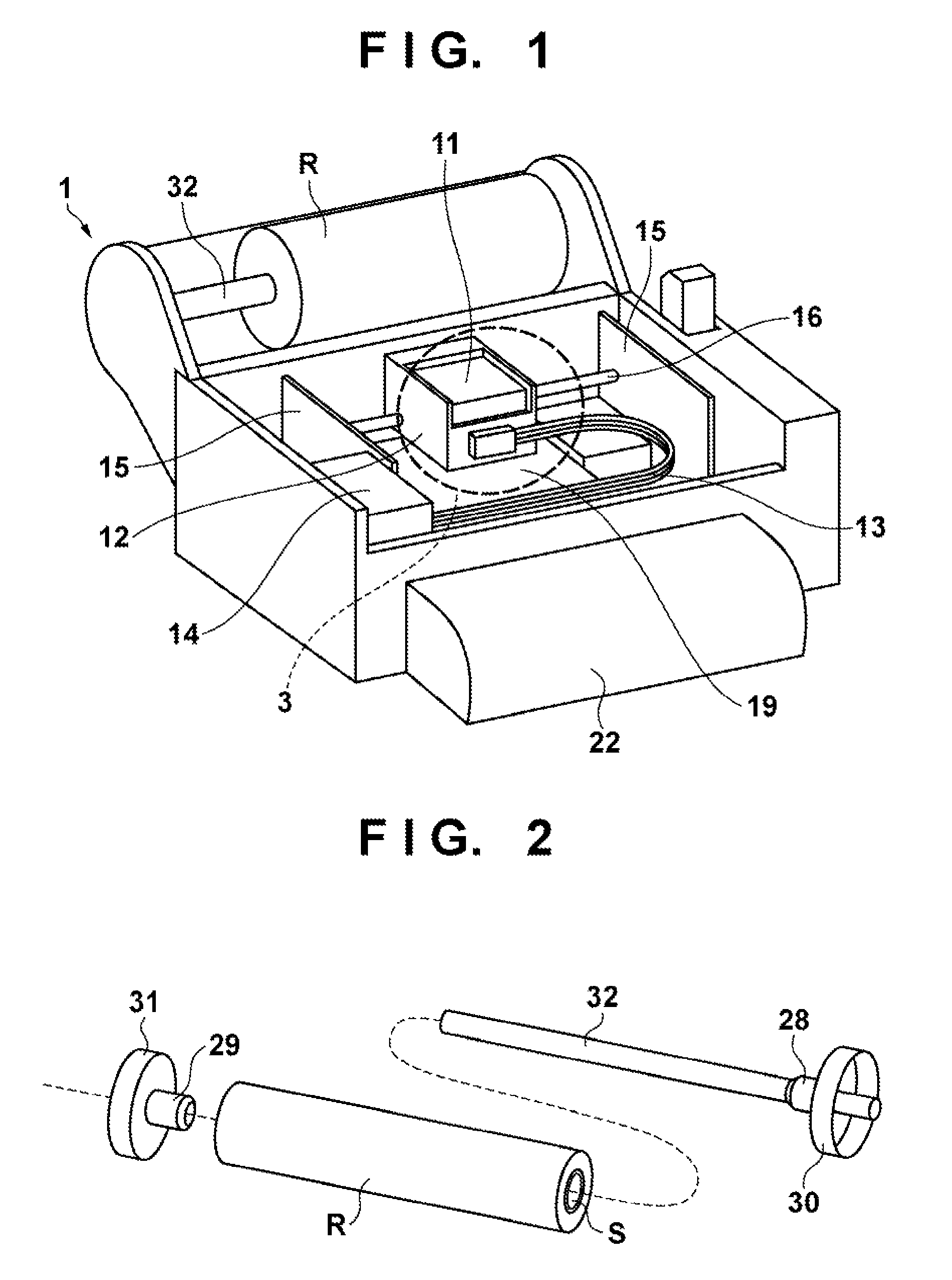
[0136]FIG. 11 is a perspective view showing the schematic arrangement of an inkjet printing apparatus (to be referred to as a printing apparatus hereinafter) including a feed mechanism of roll paper, which performs back tension control.

[0137]The arrangement shown in FIG. 11 is the same as that shown in FIG. 1 except a sheet sensor 17 provided on a side surface of a carriage 12. The sheet sensor 17 can detect the presence / absence of a sheet and an edge of a sheet. The sheet sensor 17 can also detect the width of a sheet by reciprocally operating the carriage 12. The sheet sensor 17 can also detect the skewed amount of a sheet by conveying the sheet by a predetermined a...

third embodiment

[0192]FIG. 19 is a block diagram showing a control arrangement according to still another embodiment in the feed mechanism of the printing apparatus shown in FIG. 11. Note that referring to FIG. 19, the same reference numerals as in FIG. 8 or 14 denote the same constituent elements already described there, and a description thereof will be omitted. FIG. 19 is different from FIG. 14 in the conveyance motor driving method in the first control unit. In this embodiment, a conveyance motor 8 is driven by open loop control, like a pulse motor or a stepping motor. In such an arrangement, the first control unit determines the target value of the current to drive the conveyance motor and outputs a pulse table value PTABLE corresponding to the target value to a motor driver 55. The conveyance motor 8 is driven in accordance with the pulse table value PTABLE that is, by the current having the target value determined by the first control unit. An LF control unit 43 outputs the target value of t...


PUM


Abstract

This invention has been made to cause a printing apparatus for conveying roll paper and performing printing to simultaneously attain a stable conveyance accuracy and prevent skewed conveyance independently of LF roller driving conditions and disturbance conditions that variously change as the roll paper state changes. For this purpose, a feed motor is used as a load generator for the roll paper. A section from a conveyance operation by the LF roller to the next conveyance operation is divided into a plurality of sub-sections. A feed mechanism is controlled by switching between a feeder load generation section and a feeder load zero section for each sub-section.

Description

BACKGROUND OF THE INVENTION[0001]Field of the Invention[0002]The present invention relates to a printing apparatus, a conveyance apparatus, and a conveyance control method. Particularly, the present invention relates to a printing apparatus that stabilizes a back tension variation during, for example, roll paper conveyance by a conveyance roller, a conveyance apparatus, and a roll paper conveyance control method in the apparatus.[0003]Description of the Related Art[0004]There are printing apparatuses that use large paper having a size of A2 or more. A printing apparatus of this type often uses roll paper (a rolled portion where a sheet is wound will be referred to as roll paper, and a portion pulled out from the roll paper will be referred to as a sheet portion hereinafter) in addition to sheets. The sheet portion is pulled out from the roll paper by rotating a conveyance roller. However, since the roll paper is heavy in weight, a large force is necessary for pulling out the sheet p...

Claims


Application Information

Patent Timeline
Patent Type & Authority Patents(United States)
IPC IPC(8): B65H23/18B41J11/42B41J15/04
CPCB41J15/04B41J11/42
Inventor TANAMI, HARUHIKOIGARASHI, YUKISHINJO, RYOYAMARUYAMA, RYOHEIGENTA, SHINWAKAYAMA, NAOKI
Owner CANON KK
Why Eureka
Try Eureka