Systems and methods for safe compliant insertion and hybrid force/motion telemanipulation of continuum robots

a technology of continuum robots and hybrid force/motion, applied in the field of systems and methods of controlling the position and pose of multi-segment continuum robots, can solve the problems of limited adoption of continuum robots, significant disadvantages for exploration and intervention in unstructured environments, and limited accuracy and magnitude of passive compliant systems

Active Publication Date: 2017-01-10
VANDERBILT UNIV
View PDF174 Cites 772 Cited by
  • Summary
  • Abstract
  • Description
  • Claims
  • Application Information

AI Technical Summary

Benefits of technology

The patent describes a system and method for creating a continuum robot that can adapt to the shape of a cavity inside the body for surgical procedures. The robot is controlled by a computer algorithm that adjusts the position and shape of the robot segments as it moves deeper into the cavity. This allows for minimally invasive surgery without the need for a large incision. The technology can also be used for other procedures that require precise tool positioning, such as frontal sinus exploration and injection of material into paralyzed vocal cords. The main benefits are reduced surgery cost and improved feedback on surgical outcomes.

Problems solved by technology

However, adoption of continuum robots has been limited due to a lack of controls methods to prevent damage to the robotic structure and the environment when the device is inserted into a cavity of unknown dimensions.
Though these systems have shown promise in providing a measure of safety, they suffer from a number of significant disadvantages for exploration and intervention in unstructured environments.
By the very nature of their design, passive compliant systems are limited in their accuracy and the magnitude of forces that can be applied during environment interaction.
Conversely, the measure of safety provided by passive compliance is limited by the flexibility of the system.
Additionally, the compliance adds uncertainty and modeling difficulties that degrade trajectory tracking performance.

Method used


Image

  • Systems and methods for safe compliant insertion and hybrid force/motion telemanipulation of continuum robots
  • Systems and methods for safe compliant insertion and hybrid force/motion telemanipulation of continuum robots
  • Systems and methods for safe compliant insertion and hybrid force/motion telemanipulation of continuum robots

Examples


Embodiment Construction

[0067]Before any embodiments of the invention are explained in detail, it is to be understood that the invention is not limited in its application to the details of construction and the arrangement of components set forth in the following description or illustrated in the following drawings. The invention is capable of other embodiments and of being practiced or of being carried out in various ways.

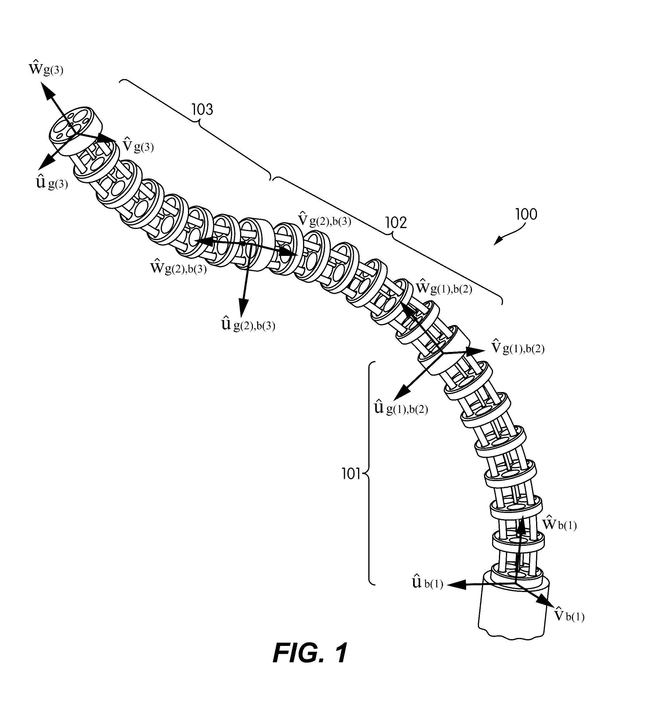
[0068]FIG. 1 illustrates a multiple-segment continuum robot 100 with multiple back-bone structures to control the movement and position of the continuum robot 100. The multiple-segment continuum robot 100 of FIG. 1 includes three independent segments 101, 102, and 103. However, other continuum robots may include more or fewer segments. In operation, a tool or other device would be extended through the continuum robot and would emerge at the distal end of the continuum robot (e.g., the open end of segment 103). The other labels and vectors illustrated in FIG. 1 are referred to below in des...


PUM


Abstract

Methods and systems are described for controlling movement of a continuum robot that includes a plurality of independently controlled segments along the length of the continuum robot. The continuum robot is inserted into a cavity of unknown dimensions or shape. A plurality of forces acting upon the continuum robot by the surrounding cavity are estimated. A positioning command indicating a desired movement of the distal end of the continuum robot is received from a manipulator control. The desired movement is augmented based, at least in part, on the estimated plurality of forces acting on the continuum robot such that movement is restricted to within safe boundaries of the surrounding cavity. The positioning of the continuum robot is then adjusted based on the augmented desired movement.

Description

RELATED APPLICATIONS[0001]This application claims priority to U.S. Provisional Application No. 61 / 819,808, filed on May 6, 2013 and titled “METHOD AND SYSTEM FOR COMPLIANT INSERTION OF CONTINUUM ROBOTS,” the entire contents of which are incorporated herein by reference.STATEMENT REGARDING FEDERALLY SPONSORED RESEARCH OR DEVELOPMENT[0002]This invention was made with government support under grant IIS-1063750 awarded by the National Science Foundation. The government has certain rights in the invention.FIELD OF THE INVENTION[0003]The present invention relates to systems and methods of controlling the position and pose of multi-segment continuum robots. More specifically, the present invention relates to systems and methods of compliant insertion of a continuum robot into a cavity of unknown size, dimensions, and structure.BACKGROUND OF THE INVENTION[0004]Multi-segment continuum robots provide for snake-like movement and positioning by deformation of internal structures of the robotic ...

Claims


Application Information

Patent Timeline
Patent Type & Authority Patents(United States)
IPC IPC(8): G05B19/18B25J9/16A61B17/00
CPCB25J9/1625A61B34/30A61B2017/00314A61B2017/00323A61B2034/306A61B2090/064G05B2219/40184G05B2219/40299Y10S901/01Y10S901/30Y10S901/50A61B34/35A61B34/37A61B90/06A61B2034/301B25J9/1602B25J9/1633
Inventor SIMAAN, NABILBAJO, ANDREANETTERVILLE, JAMES L.GARRETT, C. GAELYNGOLDMAN, ROGER E.
Owner VANDERBILT UNIV
Why Eureka
Try Eureka