
Weighted gearshift knob

a gearshift and knob technology, applied in the direction of gearing elements, mechanical control devices, instruments, etc., can solve the problems of increasing the knob attachment is subject to loosening, and the gearshift knob has many varying components, so as to optimize the handle of the gearshift, reduce the noise of the gearshift, and minimize the assembly and/or disassembly.

Inactive Publication Date: 2016-12-13
MENDEZ CARLOS JOAQUIN
View PDF16 Cites 0 Cited by
  • Summary
  • Abstract
  • Description
  • Claims
  • Application Information

AI Technical Summary

Benefits of technology

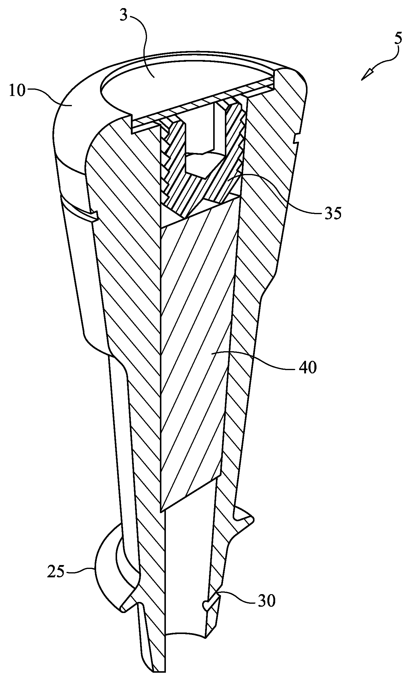
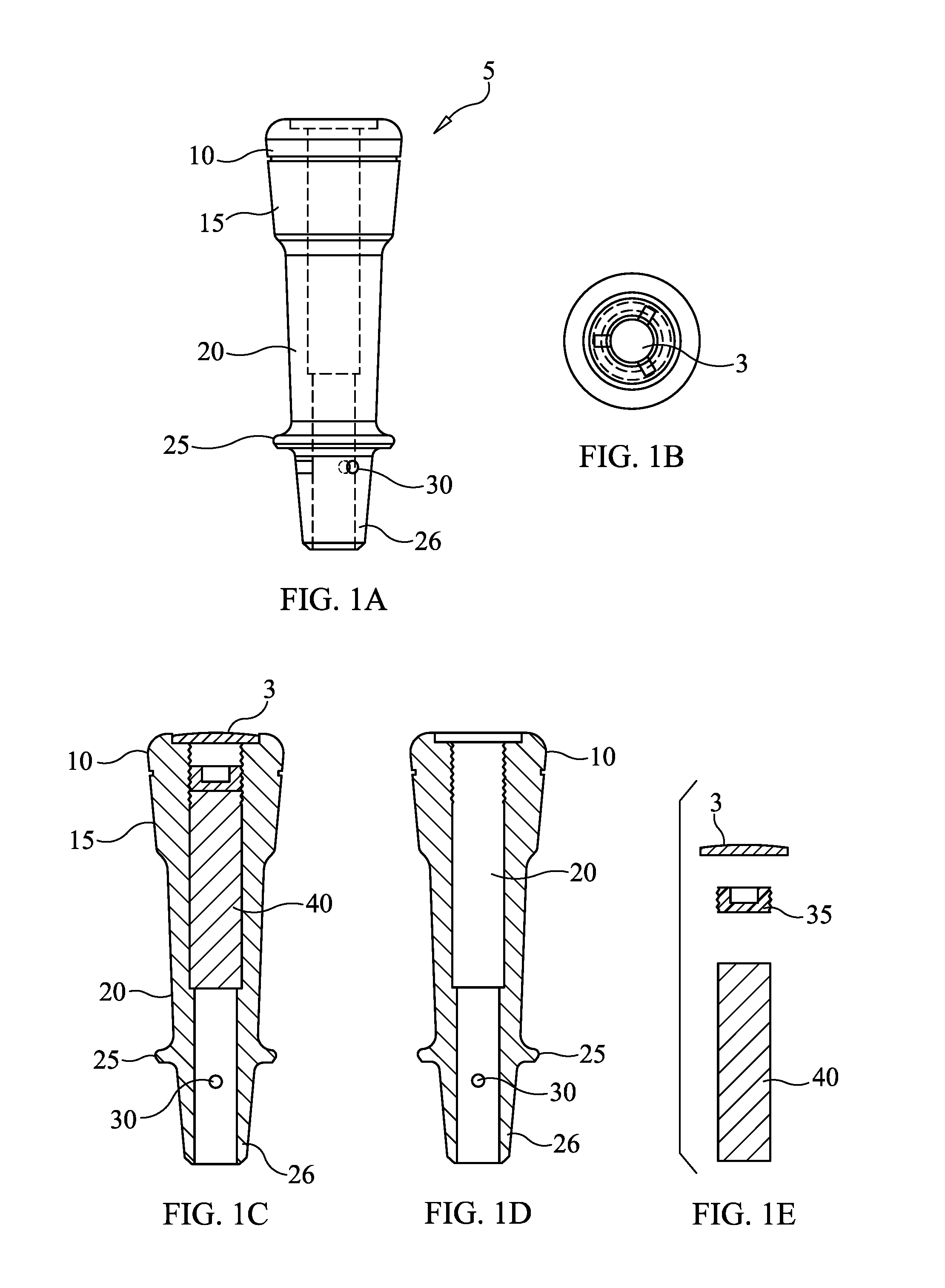
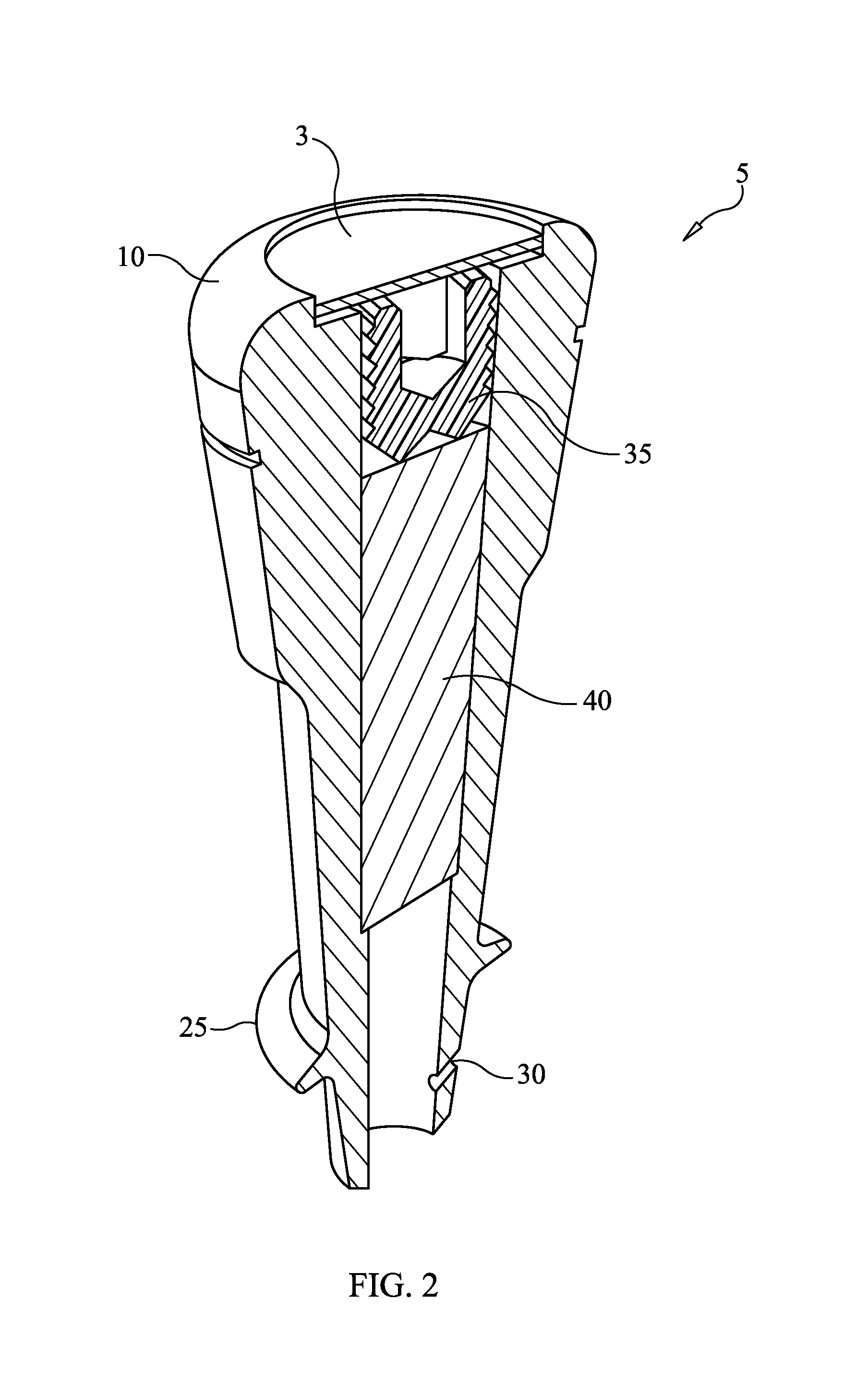
[0006]The present invention is a gearshift knob for mounting to the gearshift shaft of a motor vehicle. This invention aims to allow for the addition or removal of a counter weight through the upper portion of the gearshift knob. This gearshift knob has a cylindrical shape with a hollow interior suited for the insertion of a cylindrical weight, which weight is then secured by a removable screw, and the screw is covered by a cap. This design allows the gearshift knob and its components to be housed in one apparatus, requiring minimal assembly and / or disassembly for mounting or removal from the gearshift shaft. This gearshift knob is mounted to the gearshift shaft as one component unit and without the use of any fasteners, clips, or other attachment mechanisms for assembly. This gearshift knob is easily and securely attached to the gearshift shaft with set screws. Additionally, this gearshift knob does not require disassembly prior to removal from the gearshift shaft.
[0007]A key component of this present invention is the cylindrical weight inserted into the hollow housing that comprises the gearshift knob. This cylindrical weight is specially crafted and sized to fit snugly within the gearshift knob body in order to optimize the handle of the gearshift during racing or street driving. This snug fit is designed to maintain rigid positioning of the cylindrical weight and reduce or eliminate slippage during use. The weight acts as a counterweight during shifting and allows for weight adjustment to fit a driver's style and driving preference. Additionally, the set screws which secure the gearshift knob to the gear shaft helps to eliminate or significantly reduce the de of rotation of the knob about the shaft during intense driving and gear shifting. The stability of the attachment of the gearshift knob to the shaft via the set screws also provides the added function of eliminating the accidental slipping or separation of the knob from the shaft. In the present invention, the addition of the cylindrical weight allows the driver to have more precise shifting of gears, while the added height of the knob allows the driver to keep his hand closer to the steering wheel while shifting through gears. The design of the gearshift knob provides the driver with the assurance that the gearshift will remain securely attached to the shaft and be able to withstand the myriad and multiple quick movements under intense driving conditions.

Problems solved by technology

However, these improvements usually require that the gearshift knob have many varying components and intricate assembly utilizing tools.
Further, these improvements are subject to loosening of the knob attachment over time due to use or due to quick movements applied by a driver.
This loosening of the gearshift knob attachment results in increased noise in the gearshift as was as reduced control and performance.

Method used


Image

  • Weighted gearshift knob
  • Weighted gearshift knob
  • Weighted gearshift knob

Examples


Embodiment Construction

[0019]Before the subject invention is described further, it is to be understood that the invention is not limited to the particular embodiments of the invention described below, as variations of the particular embodiments may be made and still fall within the scope of the invention. It is also to be understood that the terminology employed is for the purpose of describing particular embodiments, and is not intended to be limiting.

[0020]The details of one or more embodiments of the invention are set forth in the accompanying drawings and the description below. Other features, objects, and advantages of the invention will be apparent from the description and drawings, and from the claims. In the following description, numerous specific details are set forth to provide a thorough understanding of the embodiments. One skilled in the art to which this invention belongs will recognize, however, that the techniques described can be practiced without one or more of the specific details, or ...


PUM


Abstract

The present invention is a weighted gearshift knob for mounting to the gearshift shaft of a motor vehicle. The weighted gearshift knob comprises of a cylindrical exterior body with a hollow cylindrical interior for housing a cylindrical counter weight, which weight is secured by a removable screw, and said screw is covered by a cap. The weighted gearshift knob is designed to allow for the addition or removal of the counter weight as desired by a driver in order to achieve optimal performance. This design allows the gearshift knob and its components to be housed in one apparatus, requiring minimal assembly and / or disassembly for mounting or removal from the gearshift shaft.

Description

CROSS-REFERENCE TO RELATED APPLICATIONS[0001]This application claims the benefit of U.S. Provisional Application No. 62 / 060,025 filed on Oct. 6, 2014. The entire disclosure of this prior application is hereby incorporated by reference.STATEMENT REGARDING FEDERALLY SPONSORED RESEARCH OR DEVELOPMENT[0002]This invention has been created without the sponsorship or funding of any federally sponsored research or development program.FIELD OF THE INVENTION[0003]The present invention relates generally to a weighted shift knob for motor vehicles.BACKGROUND[0004]This invention relates to a weighted gearshift knob for motor vehicles. In the racing or sports car enhanced performance industry, where control of a motor vehicle using quick and precise movements of a gearshift is very important, there have been many improvements to the gearshift knob. Some such improvements have been subtle, but able to revolutionize the function and style of sports cars. This present invention may appear subtle, bu...

Claims


Application Information

Patent Timeline
Patent Type & Authority Patents(United States)
IPC IPC(8): G05G1/06F16H59/02
CPCG05G1/06F16H59/0278
Inventor MENDEZ, CARLOS JOAQUIN
Owner MENDEZ CARLOS JOAQUIN
Learn More