
Oven appliance

a technology for ovens and ovens, applied in ovens, ovens, domestic stoves or ranges, etc., can solve problems such as difficult and slow adjustment of pizza oven operation to account for temperature gradients, and uneven heating of pizzas on pizza stones

Active Publication Date: 2016-08-23
HAIER US APPLIANCE SOLUTIONS INC
View PDF16 Cites 9 Cited by
  • Summary
  • Abstract
  • Description
  • Claims
  • Application Information

AI Technical Summary

Benefits of technology

The present invention is an oven appliance with a baking stone positioned at the bottom of the cooking chamber. The appliance has a controller that can independently operate each of the heating elements and temperature sensors. The heating elements include an upper heating element array and a lower heating element array. The temperature sensors are positioned adjacent to the heating elements to measure the temperature. The controller can independently control the first and second zones of the upper heating element array, as well as the first and second zones of the lower heating element array. This allows for more precise control of the heating process and ensures consistent cooking results.

Problems solved by technology

Uniformly heating food items within pizza ovens operating at high temperatures poses challenges.
For example, high temperature gradients within a pizza stone of the pizza oven can unevenly heat a pizza on the pizza stone.
However, adjusting operation of the pizza oven to account for such temperature gradients can be difficult and slow.

Method used


Image

  • Oven appliance
  • Oven appliance
  • Oven appliance

Examples


Embodiment Construction

[0018]Reference now will be made in detail to embodiments of the invention, one or more examples of which are illustrated in the drawings. Each example is provided by way of explanation of the invention, not limitation of the invention. In fact, it will be apparent to those skilled in the art that various modifications and variations can be made in the present invention without departing from the scope or spirit of the invention. For instance, features illustrated or described as part of one embodiment can be used with another embodiment to yield a still further embodiment. Thus, it is intended that the present invention covers such modifications and variations as come within the scope of the appended claims and their equivalents.

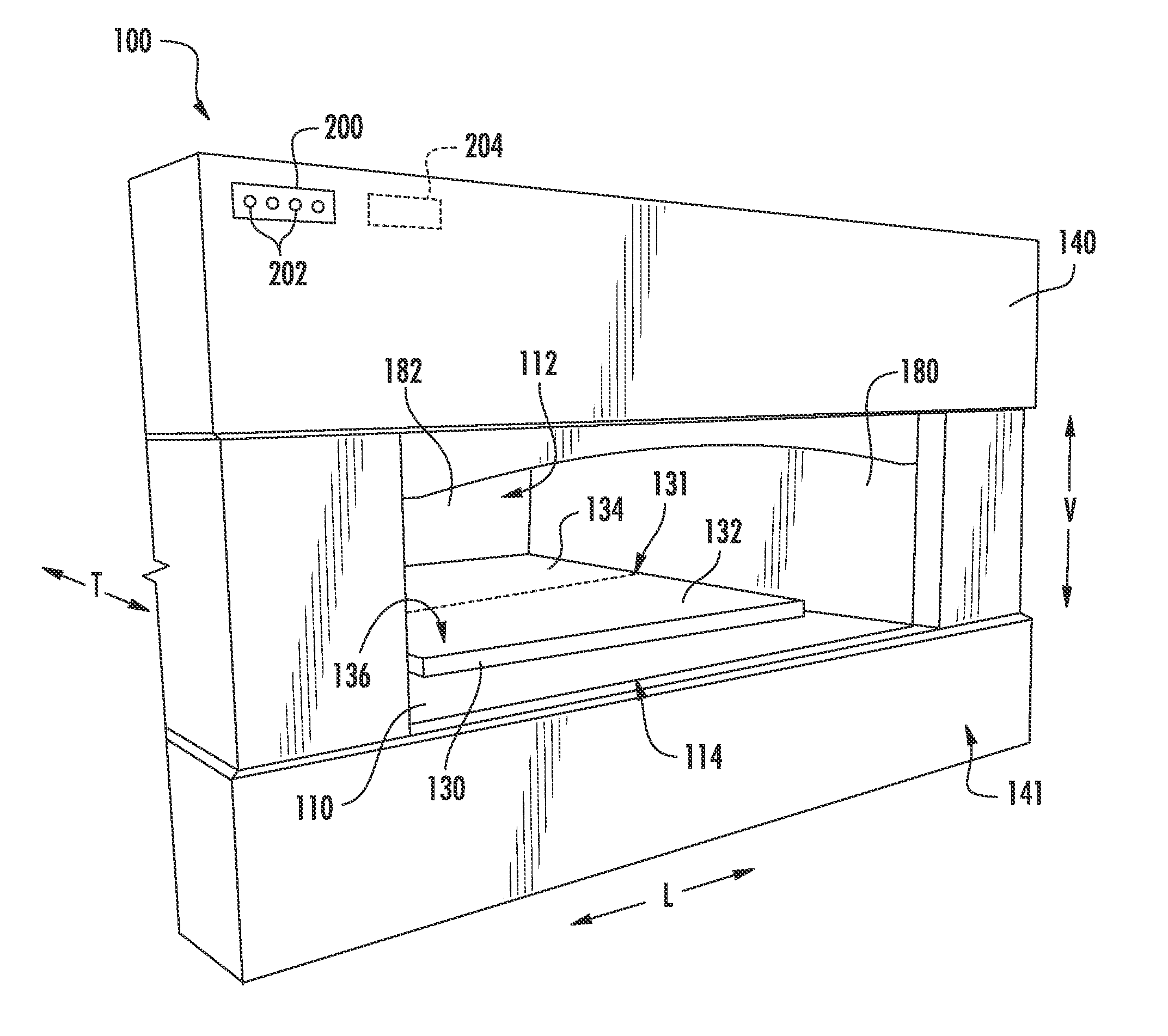
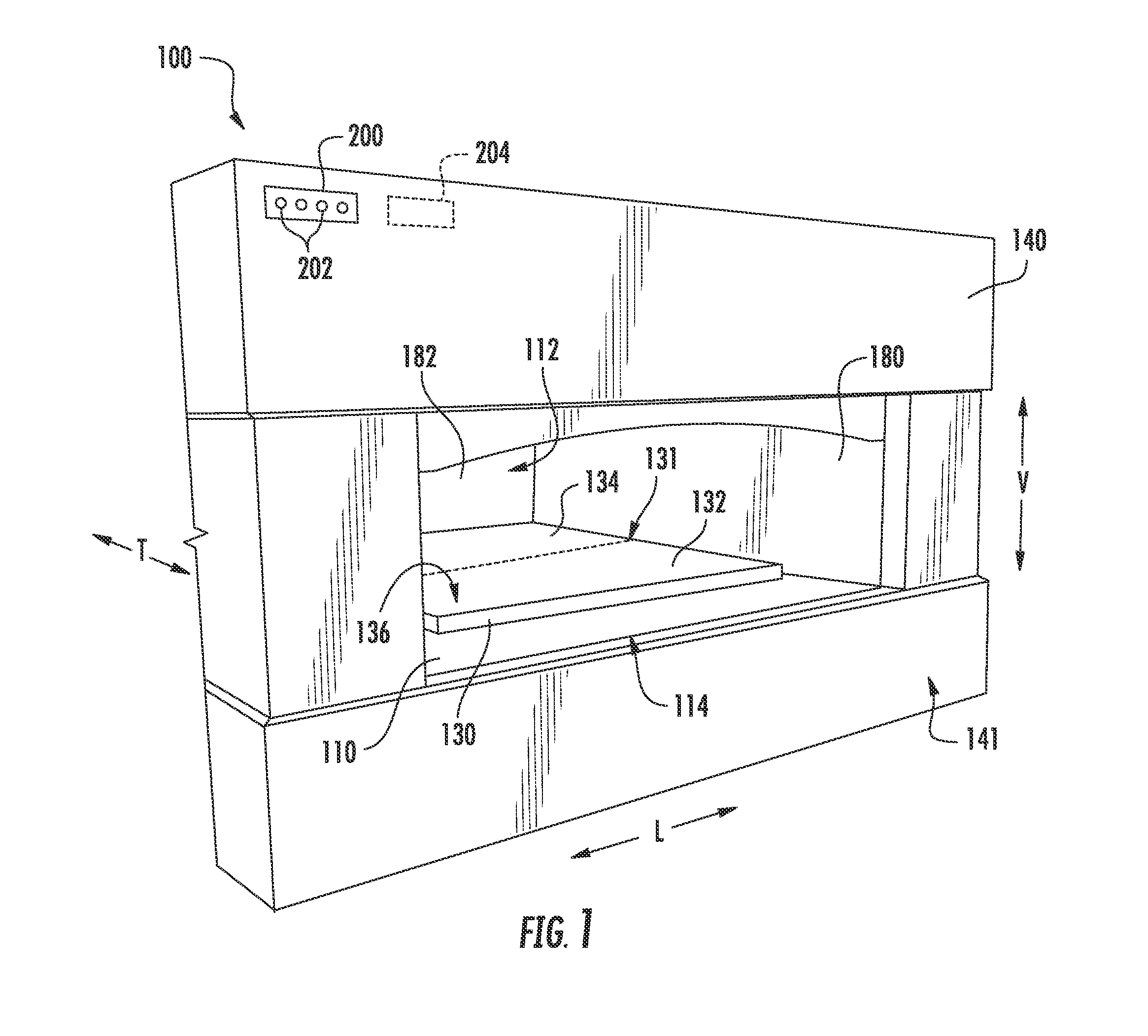
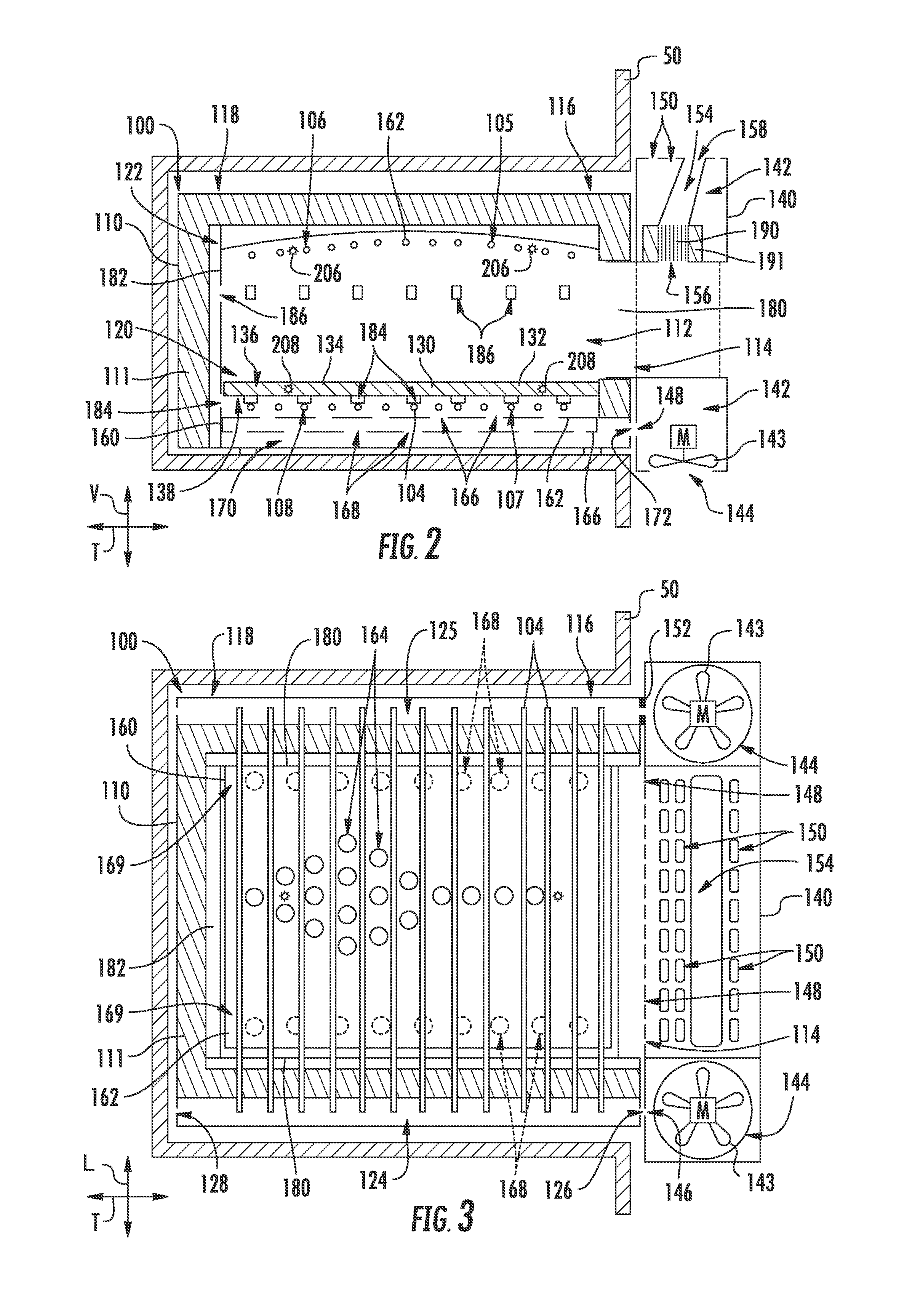
[0019]FIG. 1 provides a partial front, perspective view of an oven appliance 100 according to an exemplary embodiment of the present subject matter. As may be seen in FIG. 1, oven appliance 100 includes a housing 110 that defines a cooking chamber 112. Cook...


PUM


Abstract

An oven appliance includes a baking stone positioned within a housing at a bottom portion of a cooking chamber. A controller is in operative communication with an upper heating element array, a lower heating element array, a pair of upper temperature sensors and a pair lower temperature sensors. The controller is configured for independently operating each of a first zone of the upper heating element array, a second zone of the upper heating element array, a first zone of the lower heating element array and a second zone of the lower heating element array.

Description

FIELD OF THE INVENTION[0001]The present subject matter relates generally to oven appliances, such as pizza oven appliances.BACKGROUND OF THE INVENTION[0002]Pizza ovens generally include a housing that defines a cooking chamber for receiving a pizza for cooking Heating elements, such as gas burners, or combusting wood heat the cooking chamber to a suitable temperature. Certain pizza ovens operate at high temperatures. For example, the operating temperatures of such pizza ovens can be higher than five hundred degrees Fahrenheit.[0003]Uniformly heating food items within pizza ovens operating at high temperatures poses challenges. For example, high temperature gradients within a pizza stone of the pizza oven can unevenly heat a pizza on the pizza stone. However, adjusting operation of the pizza oven to account for such temperature gradients can be difficult and slow.[0004]Accordingly, a pizza oven with features for evenly heating a pizza stone of the pizza oven would be useful. In parti...

Claims


Application Information

Patent Timeline
Patent Type & Authority Patents(United States)
IPC IPC(8): A47J27/62A21B3/15A21B1/40A21B1/22A21B1/00A21B1/24A47J37/08A47J37/06H05B3/02H01L21/67F24C15/10
CPCA21B1/40A21B1/22A21B3/15A21B1/24H01L21/67115A47J37/0611F24C15/106A47J37/0814F24C15/006F24C15/2014
Inventor FROELICHER, STEPHEN BERNARDADELMANN, CHRISTOPHER JAMES
Owner HAIER US APPLIANCE SOLUTIONS INC
Learn More