
Stabilizer bar support device

a technology of stabilizing bar and support device, which is applied in the direction of vehicle springs, interconnection systems, vehicle components, etc., can solve the problems of abnormal noise (stick slip noise) generated, and achieve the effect of reducing the comfort of the ride of the vehicle and handling the stability of the vehicl

Active Publication Date: 2016-07-19
TOYOTA JIDOSHA KK
View PDF9 Cites 6 Cited by
  • Summary
  • Abstract
  • Description
  • Claims
  • Application Information

AI Technical Summary

Benefits of technology

[0008]To solve such a problem, the stabilizer described in Unexamined Japanese Patent Publication No. 2013-60196 is configured such that adhesive is applied to the outer peripheral surface of the stabilizer bar and the stabilizer bar is fitted to the bush. Thereby, the opening can be prevented from being generated, however, the stabilizer bar may not slide with respect to the bush and thus, the stabilizer may be prevented from rotating about the axis of the stabilizer bar. Thereby, the suspension is unlikely to stroke vertically. Thus, the handling stability of the vehicle and the comfortability of the ride of the vehicle may be decreased.
[0009]The invention has been made to solve the aforementioned problem. The object of the invention is to provide a stabilizer bar support device in which the opening is unlikely to be generated and the stabilizer bar can slide with respect to the bush smoothly.
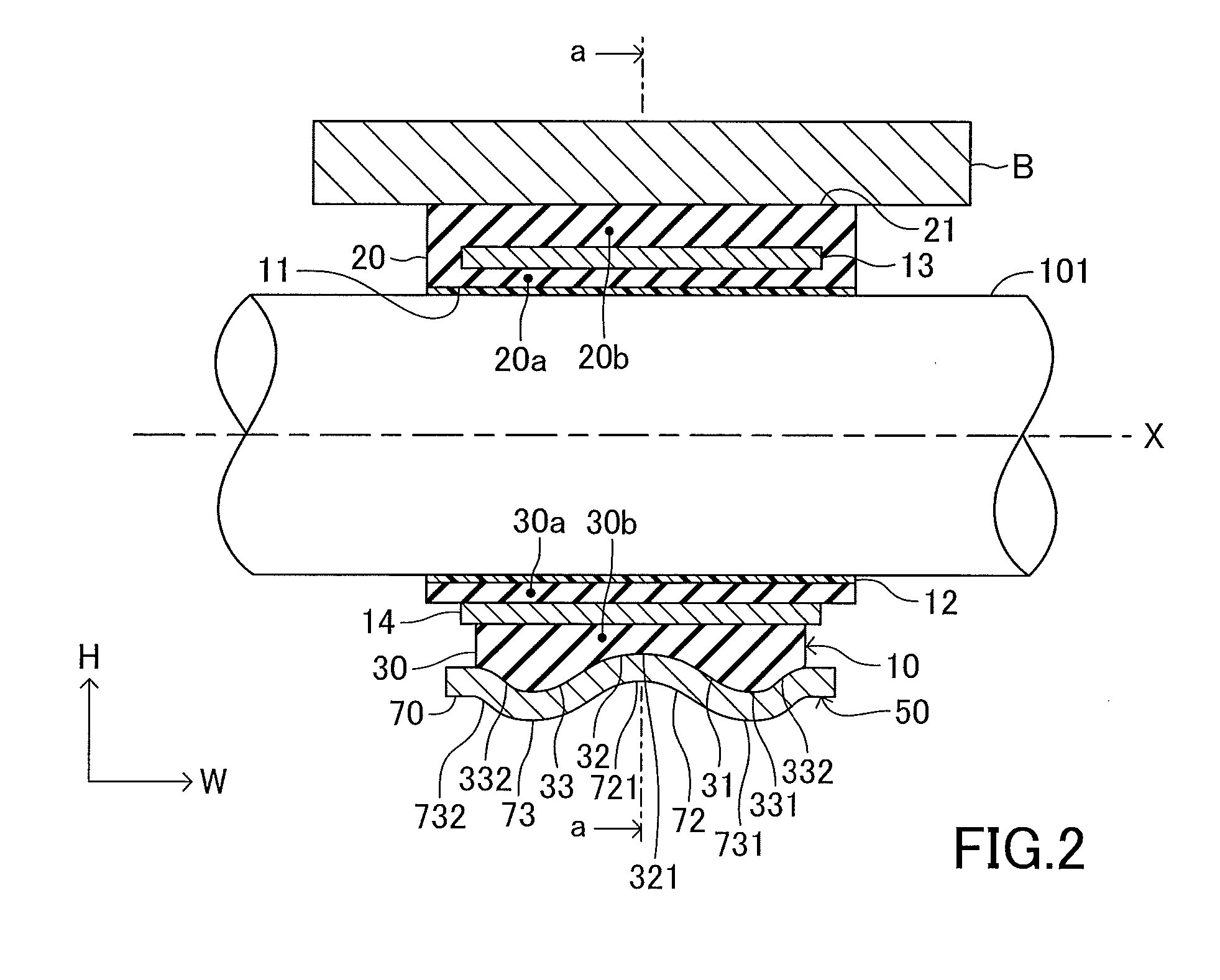
[0016]Thereby, sliding friction force can be reduced at the center part of the bush between the outer peripheral surface of the stabilizer bar and the inner peripheral surface defining the through hole when the stabilizer bar slides on the inner peripheral surface defining the through hole. Further, the opening can be prevented from being generated by setting the compressive deformation amounts of the end parts of the bush to amounts larger than the compressive deformation amount of the center part of the bush, respectively. Therefore, the compressive deformation amounts of the end parts of the bush can be set such that the openings are prevented from being generated and the compressive deformation amount of the center part of the bush can be set to an amount smaller than the respective compressive deformation amount of the respective end part of the bush. Thus, the sliding friction force can totally be reduced between the outer peripheral surface of the stabilizer bar and the inner peripheral surface defining the through hole. Thereby, the stabilizer bar can slide smoothly with respect to the bush. Thus, the handling stability and comfortability of the ride of the vehicle may be improved. Further, the contaminants may be prevented from entering into the opening.
[0023]According to one aspect of the invention, the respective mountain-like parts of the respective end parts of the bracket can hold the respective end parts of the bush with the compressive deformations of the respective end parts of the bush and the opening can be appropriately prevented from being generated. Therefore, the compressive deformation amount of the top of the mountain-like part of the bush can be set to an amount for preventing the opening from being generated. In addition, the compressive deformation amount of the bush can be set to an amount gradually decreasing from the top of the mountain-like part of the bush toward the valley-like part of the bush and the axial end part of the bush. Thus, the sliding friction force can be totally reduced between the outer peripheral surface of the stabilizer bar and the inner peripheral surface defining the through hole.
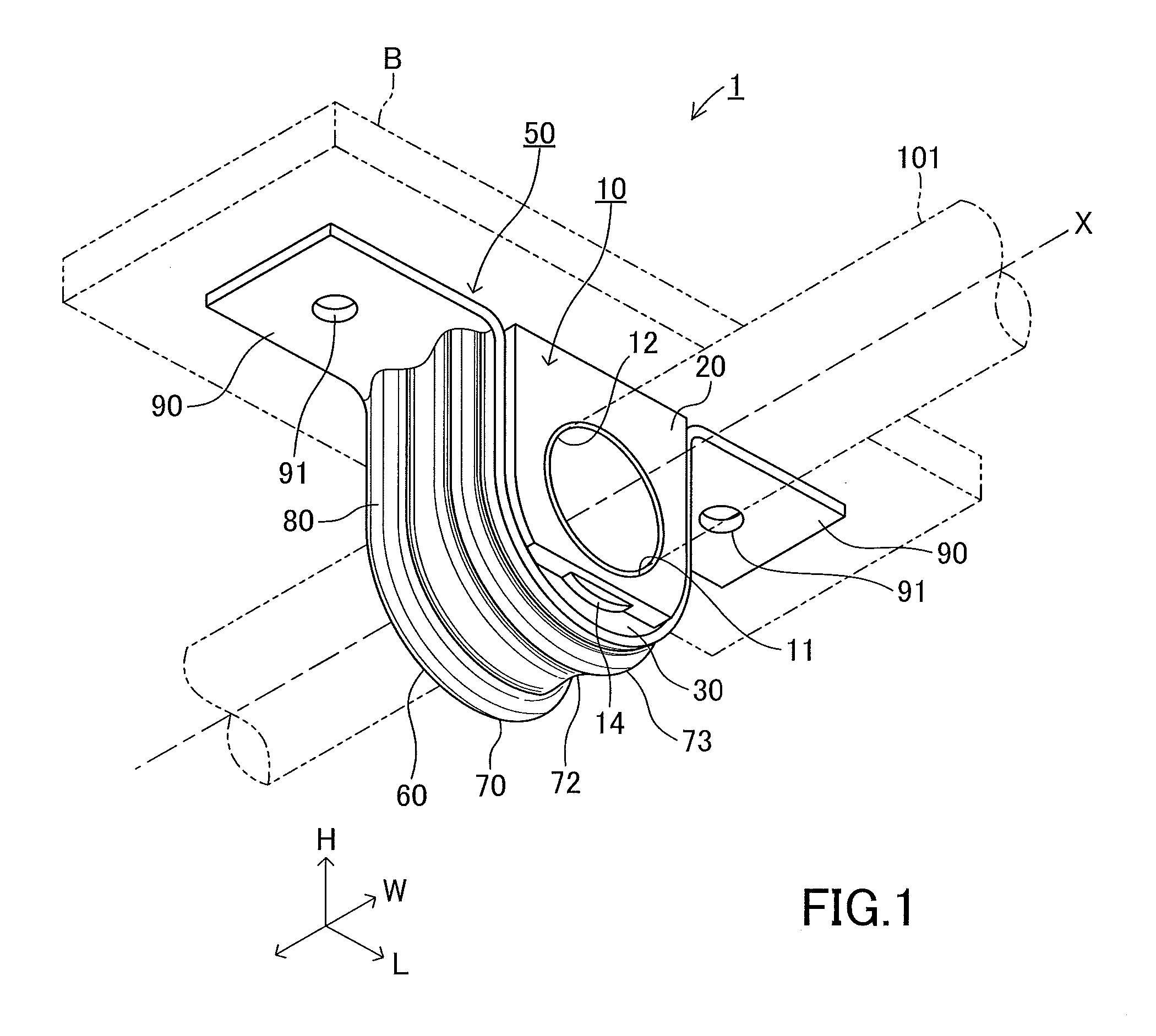
[0025]Loads act on the stabilizer about the axis of the stabilizer and vertically. The bracket according to one aspect of the invention is configured such that the bracket is fastened to the vehicle body member upwardly or downwardly with respect to the vehicle to support the stabilizer bar. Thereby, the bush is pressed in the vehicle vertical direction to resiliently support the stabilizer bar. Therefore, even when large load acts on the stabilizer bar in the vehicle vertical direction, the opening can be prevented from being generated. In addition, no large load acts on the stabilizer bar in the vehicle longitudinal direction and thus, the opening is unlikely to be generated by the vehicle longitudinal direction load. According to one aspect of the invention, the bush is configured such that the bush can be compressively deformed in the vehicle vertical direction and cannot be compressively deformed in the vehicle longitudinal direction. Thereby, the opening can be prevented from being generated and the sliding friction force can be further reduced between the outer peripheral surface of the stabilizer bar and the inner peripheral surface defining the through hole of the bush. In addition, the bracket can be mounted on the bush without compressively deforming the bush and the bracket can be easily mounted on the bush.

Problems solved by technology

However, if contaminants (such as dirt and sand) enter into the opening O, abnormal noise (stick slip noise) is generated due to the jamming by contaminants when the outer peripheral surface of the stabilizer bar 200 slides on the inner peripheral surface of the bush 210.

Method used


Image

  • Stabilizer bar support device
  • Stabilizer bar support device
  • Stabilizer bar support device

Examples


Embodiment Construction

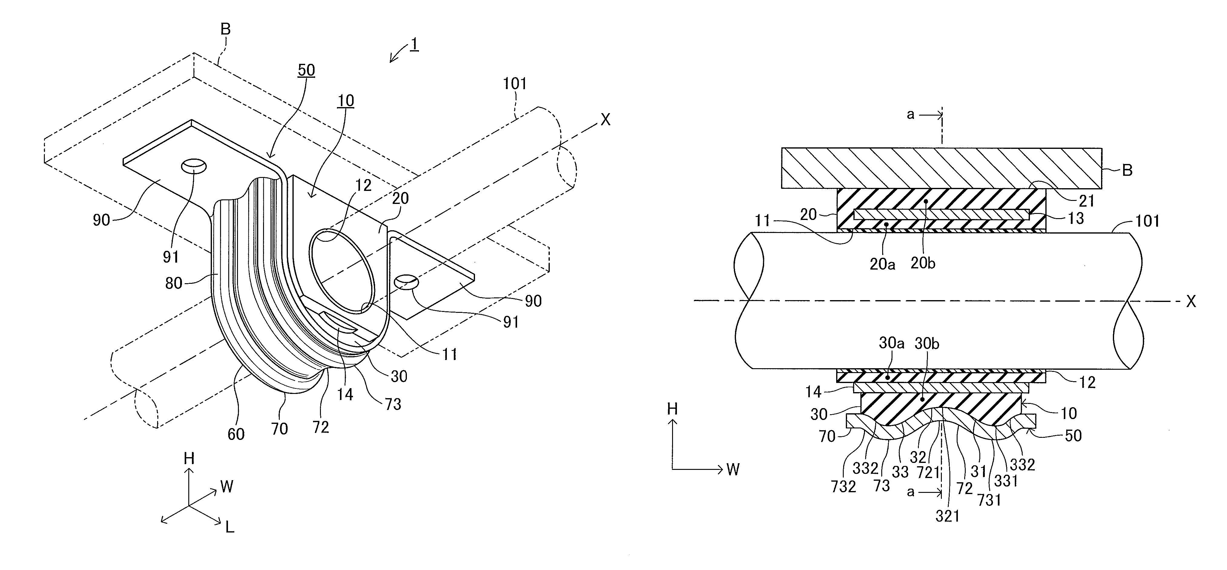
[0035]Below, a stabilizer bar support device according to an embodiment of the invention will be described with reference to the drawings. As shown in FIG. 7, a stabilizer 100 includes a rod-shaped pipe body extending between right and left wheels of a vehicle. The stabilizer 100 comprises a stabilizer bar 101 and arms 102a and 102b. The stabilizer bar 101 is positioned along a vehicle lateral direction. The arm 102a extends from one end of the stabilizer bar 101 in a vehicle longitudinal direction. The arm 102b extends from the other end of the stabilizer bar 101 in the vehicle longitudinal direction. The stabilizer 100 is formed by bending a rod-shaped pipe to include the stabilizer bar 101 and the arms 102a and 102b integral with the stabilizer bar 101. Tip ends of the arms 102a and 102b are connected to unsprung members such as lower arms of right and left suspensions not shown, respectively. The stabilizer bar 101 is twisted by a relative vertical displacement between the right...


PUM


Abstract

A stabilizer bar support device for supporting a stabilizer bar on a vehicle-body-member. The device includes a bush having a through hole, wherein the stabilizer bar is inserted; and a bracket, which has a U-shaped body-part for receiving the bush, a first fastened part extending from one end of the body-part, the first fastened part being fastened to the vehicle-body-member; a second fastened part extending from other end of the body-part, the second fastened part being fastened to the vehicle-body-member. The bush compressively deformed by being pressed by the body-part of the bracket toward the vehicle-body-member when the first and second fastened parts are fastened to the vehicle-body-member. An amount of compressive deformation of a center-part of the bush in an axial direction of the through hole is smaller than an amount of compressive deformation of an end-part of the bush in the axial direction of the through hole.

Description

BACKGROUND ART[0001]1. Field of the Invention[0002]The invention relates to a stabilizer bar support device for supporting a stabilizer bar on a vehicle body.[0003]2. Description of Related Art[0004]Conventionally, a stabilizer is known as a device for reducing a roll angle of a vehicle body. The stabilizer includes a rod body which extends between right and left wheels. The stabilizer has a stabilizer bar and arms. The stabilizer bar is positioned along a lateral direction of a vehicle and is mounted on the vehicle body. The respective arms are bent from respective opposite ends of the stabilizer bar and extend along a longitudinal direction of the vehicle. The tip ends of the arms are connected to unsprung members of lower arms or the like of suspensions, respectively. The stabilizer bar is twisted by relative displacements of the right and left arms thereof to generate reaction torsion force which reduces the roll angle when the right and left wheels stroke in an inverse phase su...

Claims


Application Information

Patent Timeline
Patent Type & Authority Patents(United States)
IPC IPC(8): F16M13/00B60G21/055
CPCB60G21/0551B60G2202/135B60G2204/1222B60G2204/41B60G2204/4307B60G2206/013
Inventor KOBAYASHI, MASAYOSHI
Owner TOYOTA JIDOSHA KK
Learn More