
Ink film constructions

a technology of ink film and construction, applied in the field of ink film construction, can solve the problems of poor image quality, unsuitable printing applications, and inability to produce images of a quality acceptable for publications such as magazines, and achieve the effect of reducing the cost of printing, and improving the quality of printing

Active Publication Date: 2016-05-03
LANDA
View PDF221 Cites 44 Cited by
  • Summary
  • Abstract
  • Description
  • Claims
  • Application Information

AI Technical Summary

Benefits of technology

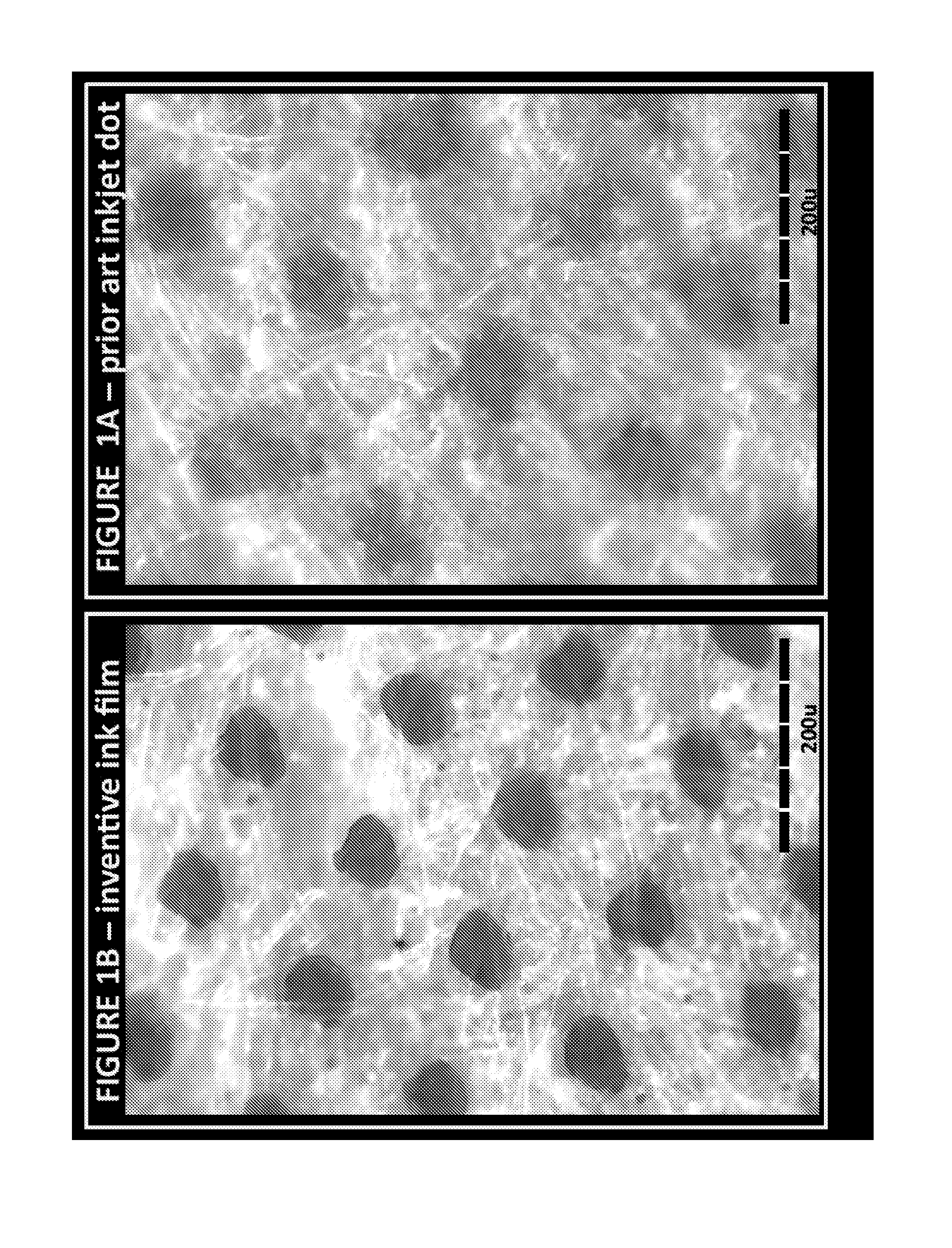
The patent describes that the ink dots have adhesion failures when tested using a tape. The technical effect is that the ink dots do not stick to the tape easily.

Problems solved by technology

Color laser printers using dry toners are suitable for certain applications, but they do not produce images of a quality acceptable for publications such as magazines.
For example, inkjet printing directly onto porous paper, or other fibrous material, results in poor image quality because of variation of the distance between the print head and the surface of the substrate, and because of the substrate acting as a wick.
Using specially coated substrates is, however, a costly option that is unsuitable for certain printing applications.
Furthermore, the use of coated substrates creates its own problems in that the surface of the substrate remains wet and additional costly steps are needed to dry the ink so that it is not later smeared as the substrate is being handled, for example stacked or wound into a roll.
Furthermore, excessive wetting of the substrate causes cockling and makes printing on both sides of the substrate (also termed perfecting or duplex printing) difficult, if not impossible.

Method used


Image

  • Ink film constructions
  • Ink film constructions
  • Ink film constructions

Examples


example 2

[0149]An inkjet ink formulation was prepared containing:

[0150]

IngredientFunctionwt. %PV Fast Blue BG (Clariant)Pigment2.3Neocryl BT-9 (40% waterResin16.5dispersion) (DSM resins)Glycerol (Aldrich)Water-miscible3.3co-solventCapstone FS-65 (DuPont)Non-ionic0.1fluorosurfactantWater (distilled)—Balance to 100%Joncryl HPD 296 (35.5%Dispersant3.2 (solid resin)water solution) (BASF)Diethyleneglycol (Aldrich)Water-miscible20co-solventDiethyl amine (Aldrich)pH adjustment1(basic)

Preparation Procedure:

[0151]A pigment concentrate, containing pigment (14%), water (79%) and Joncryl HPD 296 (7%) were mixed and milled. The progress of milling was controlled on the basis of particle size measurements (Malvern, Nanosizer). The milling was stopped when the average particle size (d50) reached 70 nm. The remaining materials were then added to the pigment concentrate and mixed. After mixing, the ink was filtered through a 0.5 μm filter.

[0152]At 25° C., the viscosity of the ink thus obtained was about 13 c...

example 3

[0153]An inkjet ink formulation was prepared containing:

[0154]

IngredientFunctionwt. %Jet Magenta DMQ (BASF)Pigment2.3Neocryl BT-26 (40% waterResin17.5dispersion) (DSM resins)Monoethanol aminepH adjustment1.5(basic)Propylene glycolWater-miscible20co-solventN-methylpyrrolidoneWater-miscible10co-solventBYK 349 (BYK)surfactant0.5(silicone)Water (distilled)—Balance to 100%

Preparation Procedure:

[0155]The pigment (10%), water (69%), Neocryl BT-26 (20%) and monoethanol amine (1%) were mixed and milled until the average particle size (d50) reached 70 nm as described in Example 2. The rest of the materials were then added to the pigment concentrate and mixed. After mixing, the ink was filtered through a 0.5 μm filter.

[0156]At 25° C., the viscosity of the ink thus obtained was about 8 cP, the surface tension was approximately 24 mN / m, and the pH was 9-10.

example 4

[0157]An inkjet ink formulation was prepared containing:

[0158]

IngredientFunctionwt. %Jet Magenta DMQ (BASF)Pigment2.2Joncryl 683 neutralizedDispersant0.6 (solid resin)with KOH (BASF)Neocryl BT-9 (40% waterResin25dispersion) (DSM resins)Ethylene glycolWater-miscible25co-solventPropylene glycolWater-miscible10co-solventPEG 400Water-miscible2co-solventGlycerolWater-miscible3co-solventBYK 349 (BYK)surfactant0.5(silicone)Water (distilled)—Balance to 100%

Preparation Procedure:

[0159]The pigment (12.3%), Joncryl 683 (3.3%) fully neutralized with a 30% solution of KOH (7.9%) and water (balance) were mixed and milled until the average particle size (d50) reached 70 nm as described in Example 2. The rest of the materials were then added to the pigment concentrate and mixed. After mixing, the ink was filtered through a 0.5 μm filter.

[0160]At 25° C., the viscosity of the ink thus obtained was about 7 cP, the surface tension was approximately 24 mN / m, and the pH was 7-8.


PUM

PropertyMeasurementUnit
diameteraaaaaaaaaa
diameteraaaaaaaaaa
side lengthaaaaaaaaaa

Abstract

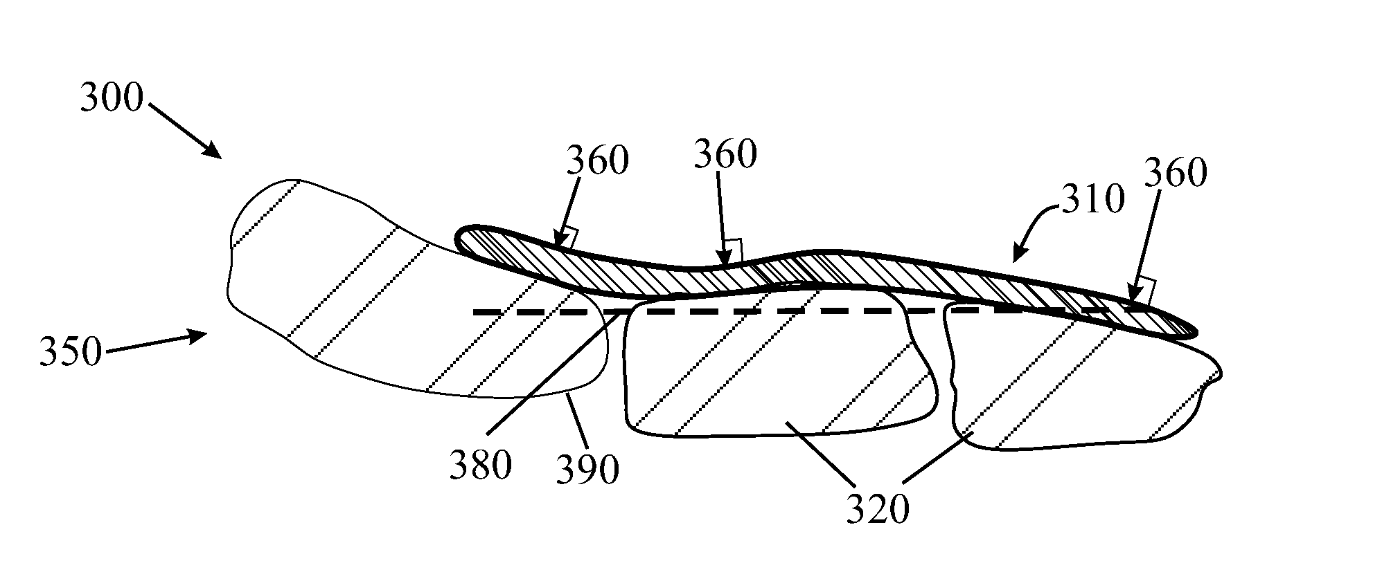
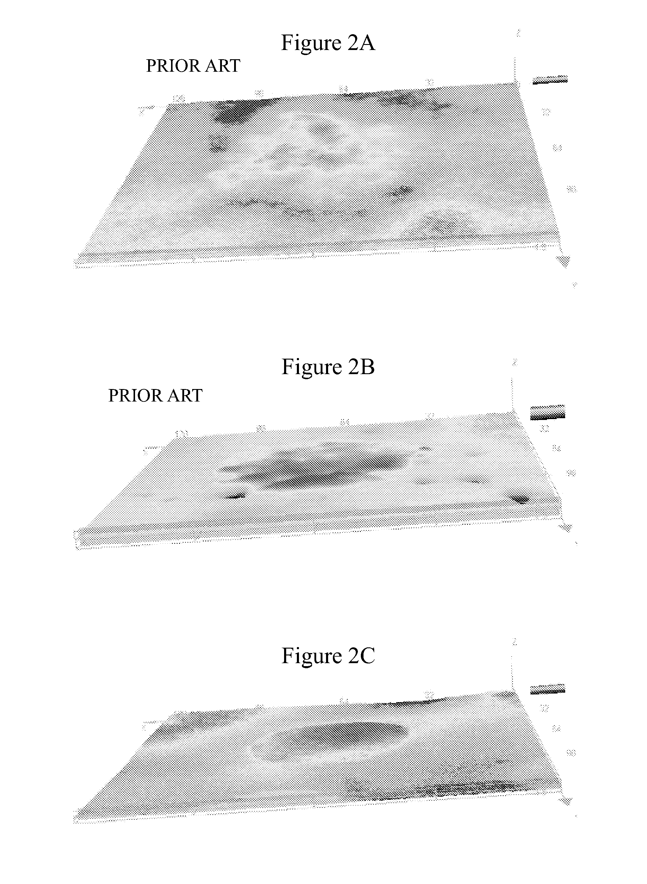
An ink film construction including: (a) a first printing substrate selected from the group consisting of an uncoated fibrous printing substrate, a commodity coated fibrous printing substrate, and a plastic printing substrate; and (b) an ink dot set contained within a square geometric projection projecting on the first printing substrate, the ink dot set containing at least 10 distinct ink dots, fixedly adhered to a surface of the first printing substrate, all the ink dots within the square geometric projection being counted as individual members of the set, each of the ink dots containing at least one colorant dispersed in an organic polymeric resin, each of the dots having an average thickness of less than 2,000 nm, and a diameter of 5 to 300 micrometers; each ink dot of the ink dots having a generally convex shape in which a deviation from convexity, (DCdot), is defined by: DCdot=1−AA / CSA, AA being a calculated projected area of the dot, the area disposed generally parallel to the first fibrous printing substrate; and CSA being a surface area of a convex shape that minimally bounds a contour of the projected area; wherein a mean deviation from convexity (DCdotmean) of the ink dot set is at most 0.05.

Description

FIELD AND BACKGROUND OF THE DISCLOSURE[0001]The present invention relates to ink film constructions and, more particularly, to ink dots adhered to printing substrates. In particular, the ink film constructions comprise continuous ink dots, which may by way of example be obtained by ink jetting technology.[0002]Currently, lithographic printing is the process in most common use for producing newspapers and magazines. Lithographic printing involves the preparation of plates bearing the image to be printed, which plates are mounted on a plate cylinder. An ink image produced on the plate cylinder is transferred to an offset cylinder that carries a rubber blanket. From the blanket, the image is applied to paper, card or another printing medium, termed the substrate, which is fed between the offset cylinder and an impression cylinder. For a wide variety of well-known reasons, offset litho printing is suitable, and economically viable, only for long print runs.[0003]More recently, digital p...

Claims


Application Information

Patent Timeline
Patent Type & Authority Patents(United States)
IPC IPC(8): B32B3/10C09D11/322B41M5/03B41M5/025B41J2/01B32B5/02D06Q1/00D06P3/00D06P1/00B05D1/00
CPCB41J2/01B32B3/10B32B5/02B41M5/0256B41M5/03C09D11/322B05D1/00D06P1/00D06P3/00D06Q1/00Y10T428/24802Y10T428/24934C09D11/037C09D11/10C09D11/107C09D175/08C09D133/08C09D11/324D21H19/58C09D183/04D21H19/62
Inventor LANDA, BENZIONABRAMOVICH, SAGIGOLODETZ, GALIANAKHMANOVICH, GREGORYASHER, ALONLITVAK, MATTETYAHU
Owner LANDA
Learn More