
Modular distractor for use in ankle surgery

Active Publication Date: 2016-04-19
INNOVATIVE MEDICAL PRODS
View PDF19 Cites 10 Cited by
  • Summary
  • Abstract
  • Description
  • Claims
  • Application Information

AI Technical Summary

Benefits of technology

The patent describes a device used in joint distraction surgery that helps to hold the joint in a specific position during surgery. One end of the device is attached to a support frame on the operating table, and the other end is positioned under the patient's knee to provide traction to the ankle. The ankle is then secured by a strap to the support frame. This device helps to keep the joint stable and secure during surgery, which can improve the accuracy of the procedure and make it safer for the patient.

Problems solved by technology

The use of such equipment in the vicinity of the ankle could impair circumferential access to the patient's foot and ankle, during surgery, under some circumstances.

Method used


Image

  • Modular distractor for use in ankle surgery
  • Modular distractor for use in ankle surgery
  • Modular distractor for use in ankle surgery

Examples


Embodiment Construction

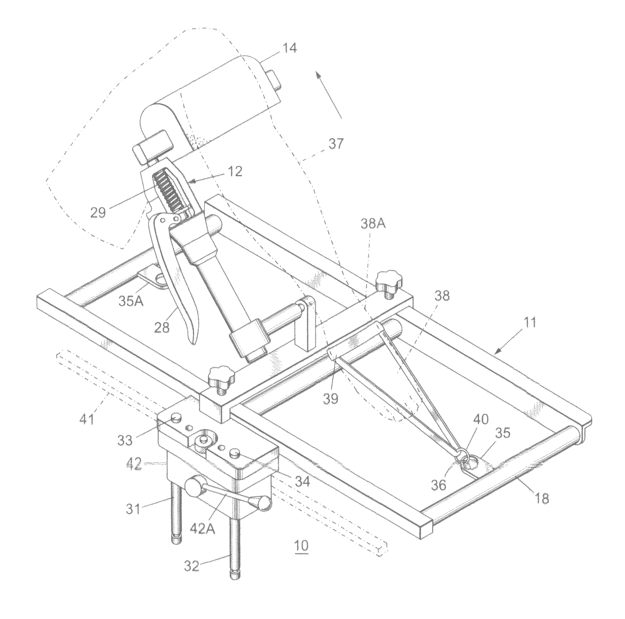
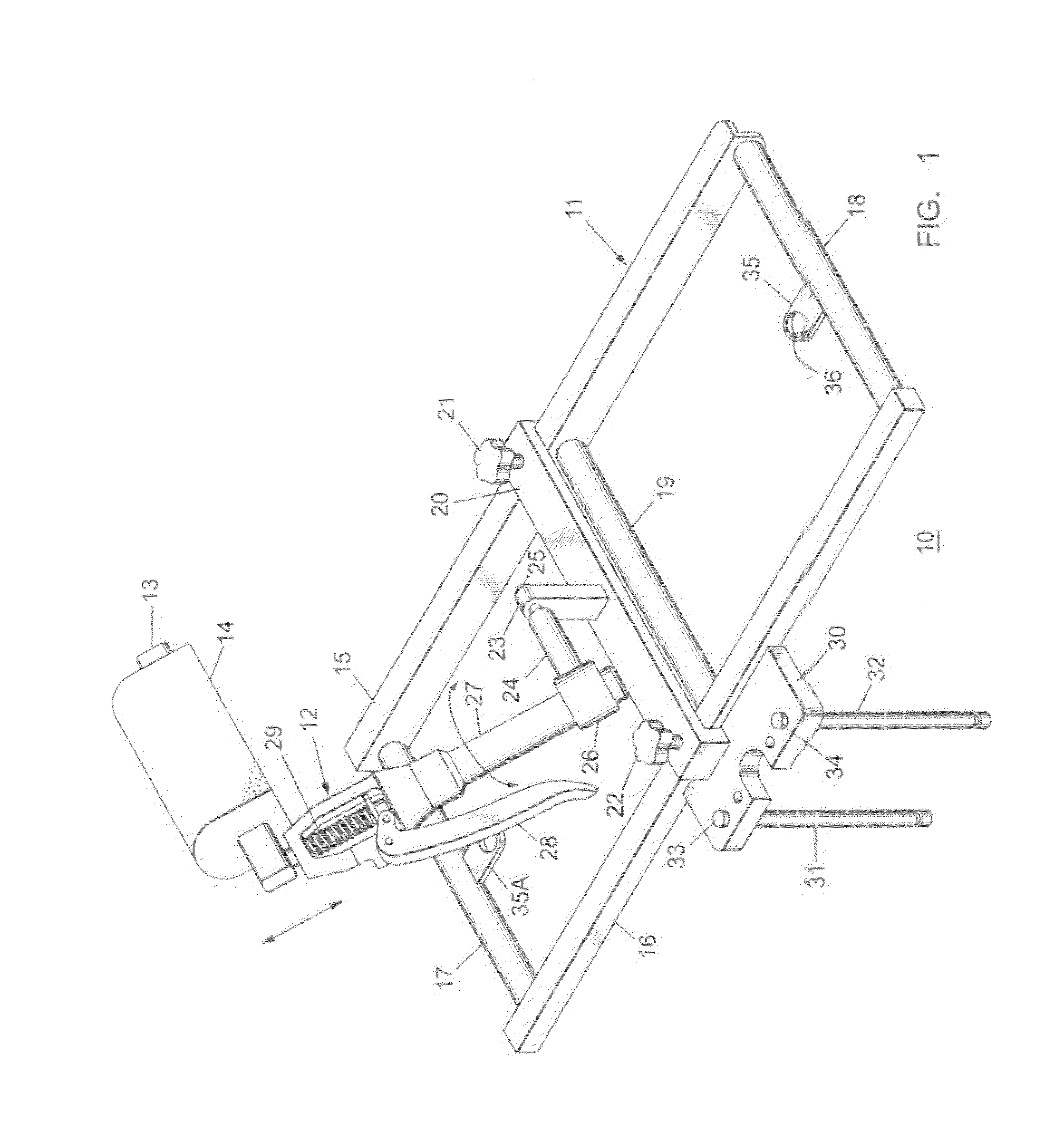
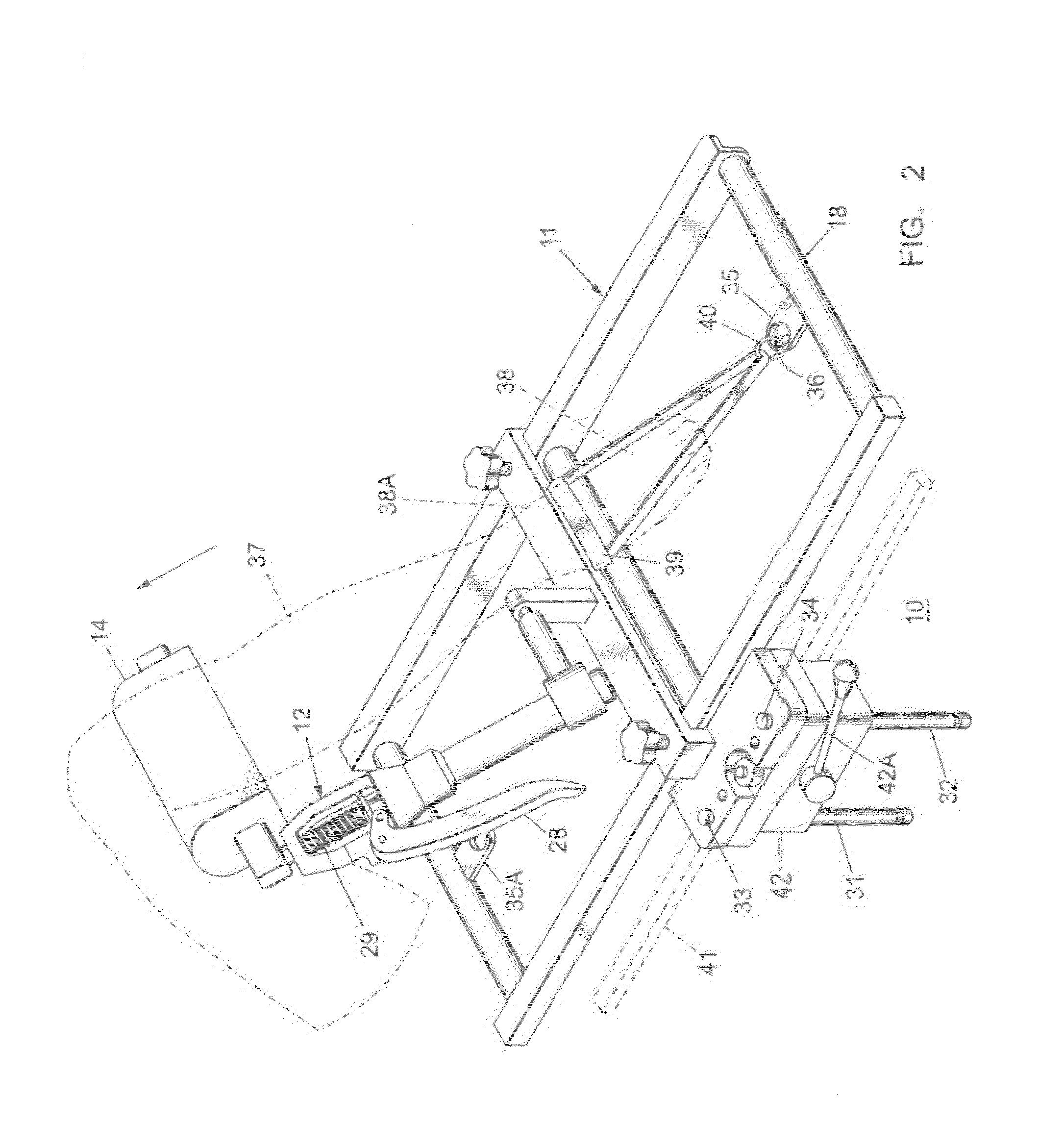
[0009]As shown in FIG. 1, the modular ankle distractor unit 10 includes a support frame 11 and a manual distractor 12, which includes a support bar 13 for the patient support pad 14 for moving the support pad in the up and down directions, as indicated, in combination with the compression spring 29 and the distractor operating handle 28.

[0010]The manual distractor 12 is described within U.S. Pat. No. 8,048,082 entitled “Non-Invasive Femoral Distractor, which Application is incorporated herein for purposes of reference.

[0011]The support frame 11 includes a pair of side bars 15, 16, end bars 17, 18 and center bar 19.

[0012]A support bar 20 extends between the side bars 15, 16 and is attached thereto by means of threaded knobs 21 and 22. A post 23, upstanding from the support bar 20, is attached to a rod 24 by means of a bolt 25 and the rod 24 is welded to the support collar 26.

[0013]One end of the manual distractor cylinder 27 is arranged within the support collar 26 whereby the manual...


PUM


Abstract

A manual distractor unit is mounted upon a support frame attached to an operating table side rail. A patient's knee support pad, extending from the distractor unit, is positioned under the patient's knee to provide traction to the patient's ankle, which is secured to the support frame.

Description

BACKGROUND OF THE INVENTION[0001]Methods currently available for ankle distraction procedures generally restrain the patient's leg and apply controlled pressure to the ankle for the required traction.[0002]U.S. Pat. No. 5,290,220 entitled “Non-Invasive Distraction System for Ankle Arthroscopy” and U.S. Pat. No. 5,025,802 entitled “Surgical Holding Apparatus for Distracting Ankle” both describe applying such traction to the ankle directly.[0003]The use of such equipment in the vicinity of the ankle could impair circumferential access to the patient's foot and ankle, during surgery, under some circumstances.[0004]It has been shown that by restraining the patient's ankle with a simple strap and applying pressure to the underside of the patient's knee, the ankle can be distracted while allowing the surgeon complete access to the ankle in all directions.[0005]On purpose of the instant invention is to provide a simple means of securing the patient's ankle while applying pressure to the un...

Claims


Application Information

Patent Timeline
IPC IPC(8): A61B17/60A61B17/66A61B17/02A61B17/68
CPCA61B17/66A61B2017/681A61B17/60A61B17/025A61F5/04A61G13/0036A61G13/101A61G13/1245
Inventor DEMAYO, EDWARD
Owner INNOVATIVE MEDICAL PRODS
Learn More