Anterior lesser tuberosity fixed angle fixation device and method of use associated therewith
a technology of anterior lesser tuberosity and fixation device, which is applied in the field of fixation device, can solve the problems of significant incidence of joint penetration, significant incidence of fracture reduction and fracture fixation, and insufficient mechanical strength of orientation to maintain rigid attachmen
- Summary
- Abstract
- Description
- Claims
- Application Information
AI Technical Summary
Problems solved by technology
Method used
Image

Examples
first embodiment
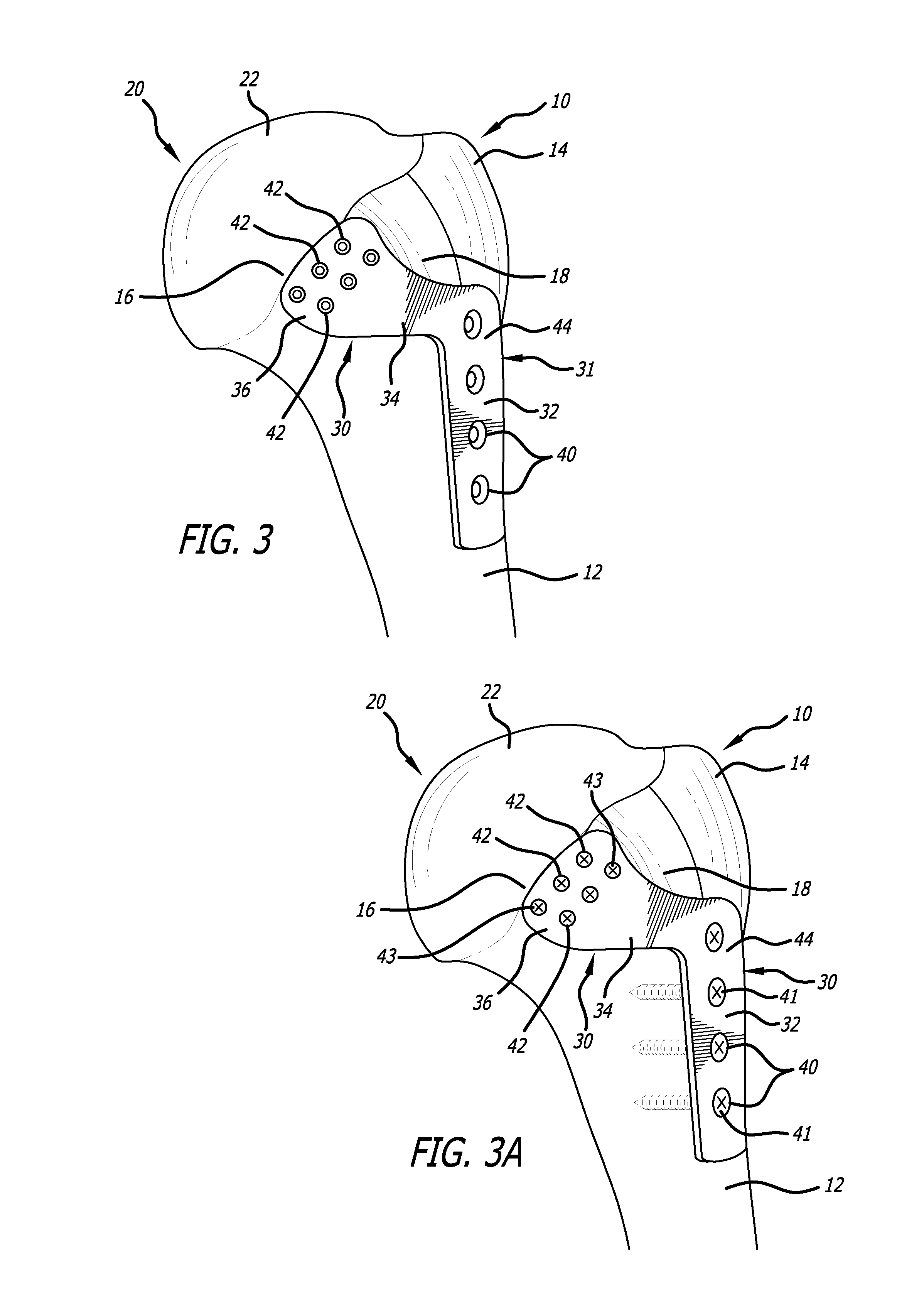
[0024]a fixation device according to the present invention is generally indicated by the numeral 30 in FIGS. 3 and 3A. Fixation device 30 includes a “dogleg-shaped” bone plate 31 and various bone screws inserted therethrough and into bone.
[0025]Bone plate 31 has a body portion 32, a neck portion 34, and an end portion 36. Body portion 32 includes apertures 40 spaced therealong, and is attached to humeral shaft 12 and portions of proximal humerus 10 using bone screws 41 (FIG. 3A) inserted through apertures 40 and into the bone. As depicted in FIGS. 3 and 3A, neck portion 34 extends from body portion 32 over biceps groove 18, and terminates at end portion 36. End portion 36 includes apertures 42 spaced apart thereon, and is attached to lesser tuberosity 16 using bone screws 43 (FIG. 3A) inserted through apertures 42 and into proximal humerus 10. Apertures 40 and 42 extend between an upper surface 44 and a lower surface (not shown) of bone plate 31. The lower surface of bone plate 31 c...
second embodiment
[0027]a fixation device according to the present invention is generally indicated by the numeral 50 in FIGS. 4 and 4A Fixation device 50 includes an “h-shaped” bone plate 51 and various screws inserted therethrough and into bone.
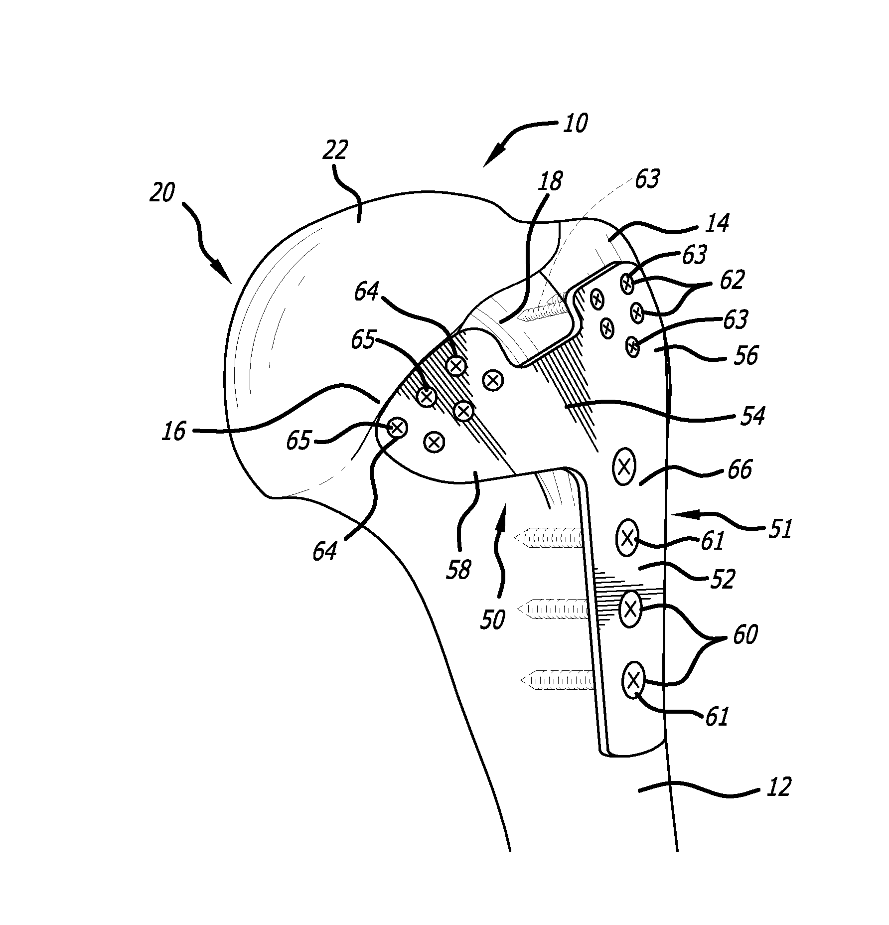
[0028]Bone plate 51 has a body portion 52, a neck portion 54, a first end portion 56, and a second end portion 58. Body portion 52 includes apertures 60 spaced therealong, and is attached to humeral shaft 12 and portions of proximal humerus 10 using bone screws 61 (FIG. 4A) inserted through apertures 60 and into the bone. As depicted in FIGS. 4 and 4A, first end portion 56 is contiguous with body portion 52, and includes apertures 62 spaced apart thereon. First end portion 56 is attached to greater tuberosity 14 using bone screws 63 (FIG. 4A) inserted through apertures 62 and into proximal humerus 10. As depicted in FIGS. 4 and 4A, neck portion 54 extends from between body portion 52 and first end portion 56 over biceps groove 18, and terminates at second en...
third embodiment
[0032]a fixation device according to the present invention is generally indicated by the numeral 70 in FIGS. 5, 5A, and 6. Fixation device 70 includes a “y-shaped” bone plate 71 and various screws inserted therethrough and into bone.
[0033]Bone plate 71 has a body portion 72, a neck portion 74, and an end portion 76. As depicted in FIGS. 5 and 5A, body portion 72 extends along greater tuberosity 14 and humeral shaft 12. Body portion 72 includes first apertures 80 and second apertures 82 formed therein. First apertures 80 are spaced apart from one another at one end of body portion 72 (ultimately adjacent greater tuberosity 14), and second apertures 82 are spaced along body portion 72 from adjacent first apertures 80 to the other end of body portion 72 (ultimately adjacent humeral shaft 12).
[0034]Furthermore, as depicted in FIG. 5, neck portion 74 extends from body portion 72 over biceps groove 18, and terminates at end portion 76. Neck portion 74 can be formed integrally with body po...
PUM
 Abstract
Description
Claims
Application Information
 - R&D
- Intellectual Property
- Life Sciences
- Materials
- Tech Scout
- Unparalleled Data Quality
- Higher Quality Content
- 60% Fewer Hallucinations
Browse by: Latest US Patents, China's latest patents, Technical Efficacy Thesaurus, Application Domain, Technology Topic, Popular Technical Reports.
© 2025 PatSnap. All rights reserved.Legal|Privacy policy|Modern Slavery Act Transparency Statement|Sitemap|About US| Contact US: help@patsnap.com