
Autonomous slat-cove-filler device for reduction of aeroacoustic noise associated with aircraft systems

a technology of aeroacoustic noise and slat cove, which is applied in the field of aircraft wings, can solve the problems of significant aircraft noise source, prominent source of airframe noise, and produced airframe nois

Active Publication Date: 2016-01-26
NASA
View PDF14 Cites 12 Cited by
  • Summary
  • Abstract
  • Description
  • Claims
  • Application Information

AI Technical Summary

Benefits of technology

The solution effectively reduces airframe noise by allowing the slat cove filler to deform and change shapes between deployed and retracted positions, maintaining an attached boundary layer and minimizing noise-causing flow separation, thus enhancing aerodynamic performance and noise reduction.

Problems solved by technology

Airframe noise produced by unsteady air flow around aircraft structures is a significant source of aircraft noise during landing approach.
Conventional leading-edge slat devices for high-lift are a prominent source of airframe noise.

Method used


Image

  • Autonomous slat-cove-filler device for reduction of aeroacoustic noise associated with aircraft systems
  • Autonomous slat-cove-filler device for reduction of aeroacoustic noise associated with aircraft systems
  • Autonomous slat-cove-filler device for reduction of aeroacoustic noise associated with aircraft systems

Examples


Embodiment Construction

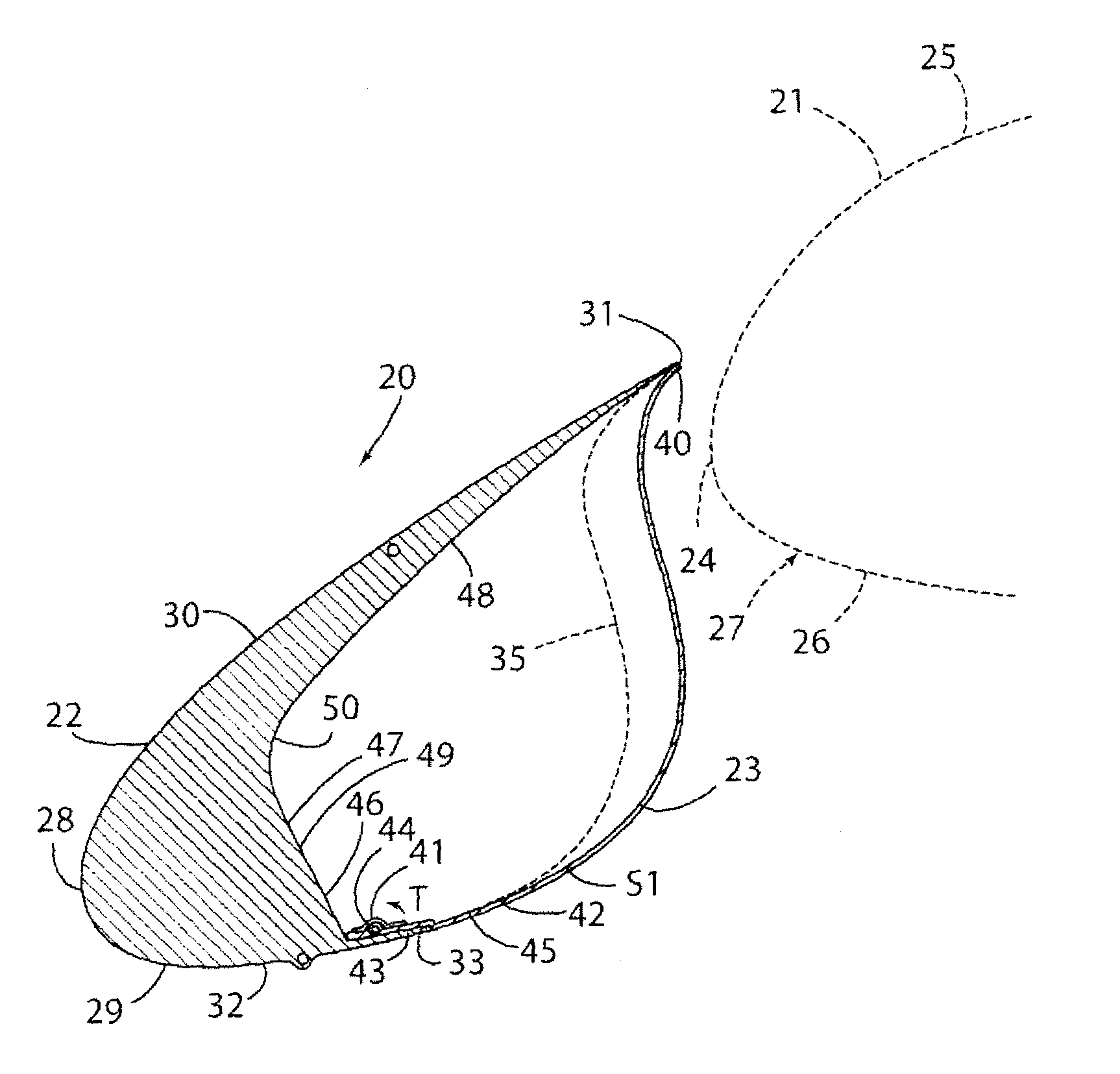
[0020]For purposes of description herein, the terms “upper,”“lower,”“right,”“left,”“rear,”“front,”“vertical,”“horizontal,” and derivatives thereof shall be related to the invention as oriented in FIG. 2. However, it is to be understood that the invention may assume various alternative orientations, except where expressly specified to the contrary. It is also to be understood that the specific devices and processes illustrated in the attached drawing, and described in the following specification are simply exemplary embodiments of the inventive concepts defined in the appended claims. Furthermore, references to specific items or features (e.g. a wing structure, leading edge slat, and slat cove filler) shall not be construed as limiting the item or feature to one-piece or multi-piece items or features. Hence, specific dimensions and other physical characteristics relating to the embodiments disclosed herein are not to be considered as limiting, unless the claims expressly state otherw...


PUM


Abstract

A slat cove filler is utilized to reduce airframe noise resulting from deployment of a leading edge slat of an aircraft wing. The slat cove filler is preferably made of a super elastic shape memory alloy, and the slat cove filler shifts between stowed and deployed shapes as the slat is deployed. The slat cove filler may be configured such that a separate powered actuator is not required to change the shape of the slat cove filler from its deployed shape to its stowed shape and vice-versa. The outer contour of the slat cove filler preferably follows a profile designed to maintain accelerating flow in the gap between the slat cove filler and wing leading edge to provide for noise reduction.

Description

CROSS-REFERENCE TO RELATED APPLICATION[0001]This application claims the benefit of and priority to U.S. Provisional Application No. 61 / 405,347 filed on Oct. 21, 2010, the entire contents of which are incorporated by reference in their entirety.STATEMENT REGARDING FEDERALLY SPONSORED RESEARCH OR DEVELOPMENT[0002]The invention described herein was made in part by employees of the United States Government and may be manufactured and used by or for the Government of the United States of America for governmental purposes without the payment of any royalties thereon or therefore.FIELD OF THE INVENTION[0003]This invention relates to aircraft wings, and in particular to a slat cove filler utilized in conjunction with a leading edge slat of an aircraft wing to reduce aero-acoustic noise associated with the slat when it is in a deployed configuration.BACKGROUND OF THE INVENTION[0004]Airframe noise produced by unsteady air flow around aircraft structures is a significant source of aircraft noi...

Claims


Application Information

Patent Timeline
Patent Type & Authority Patents(United States)
IPC IPC(8): B64C9/24B64C9/22B64C3/48
CPCB64C9/22B64C3/48B64C9/24B64C2230/14Y02T50/145Y02T50/32Y02T50/10Y02T50/30
Inventor TURNER, TRAVIS L.KIDD, REGGIE T.LOCKARD, DAVID PKHORRAMI, MEHDI R.STREETT, CRAIG L.WEBER, DOUGLAS LEO
Owner NASA
Learn More