
Staple formation recognition for a surgical device

a surgical device and formation recognition technology, applied in the field of anvil members, can solve the problems of inadvertent tissue separation, improper or incomplete staple formation, and the possibility of surgical staples encountering bone or other tough tissues

Active Publication Date: 2015-12-29
TYCO HEALTHCARE GRP LP
View PDF60 Cites 1112 Cited by
  • Summary
  • Abstract
  • Description
  • Claims
  • Application Information

AI Technical Summary

Problems solved by technology

Occasionally, staples may encounter bone or other tough tissues where they become deformed prior to crimping.
Tissue penetrating legs of the staples may become bent prior to entering the staple pockets or may become deflected or skewed aside resulting in improper or incomplete staple formation.
This may lead to inadvertent tissue separation or, in the case of tubular tissue sections, leakage contaminating the operative site.
If the knife blade passes through a poorly formed staple line in the tissue, similar problems may occur.

Method used


Image

  • Staple formation recognition for a surgical device
  • Staple formation recognition for a surgical device
  • Staple formation recognition for a surgical device

Examples


Embodiment Construction

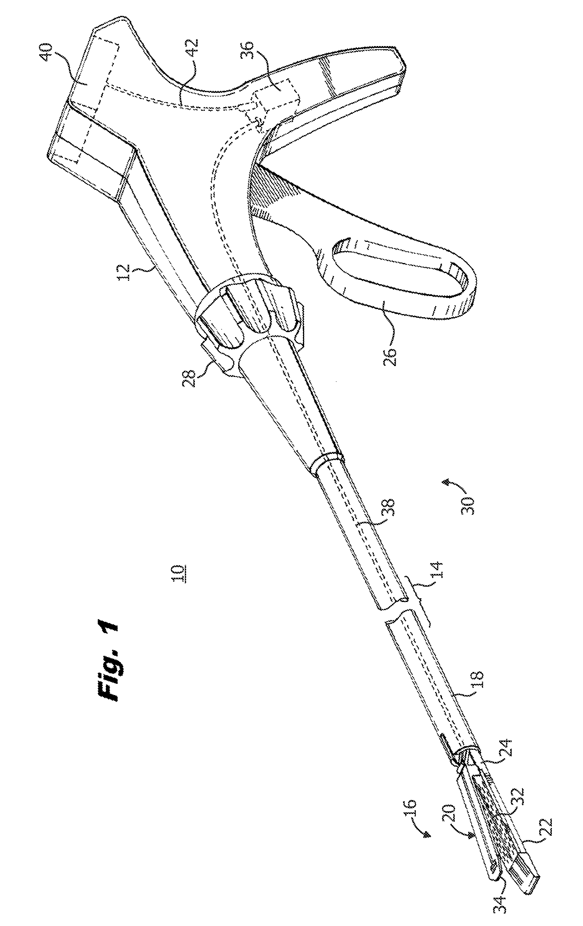
[0058]Embodiments of the presently disclosed staple formation recognition systems will now be described in detail with reference to the drawings wherein like numerals designate identical or corresponding elements in each of the several views. As is common in the art, the term ‘proximal” refers to that part or component closer to the user or operator, i.e. surgeon or physician, while the term “distal” refers to that part or component further away from the user.

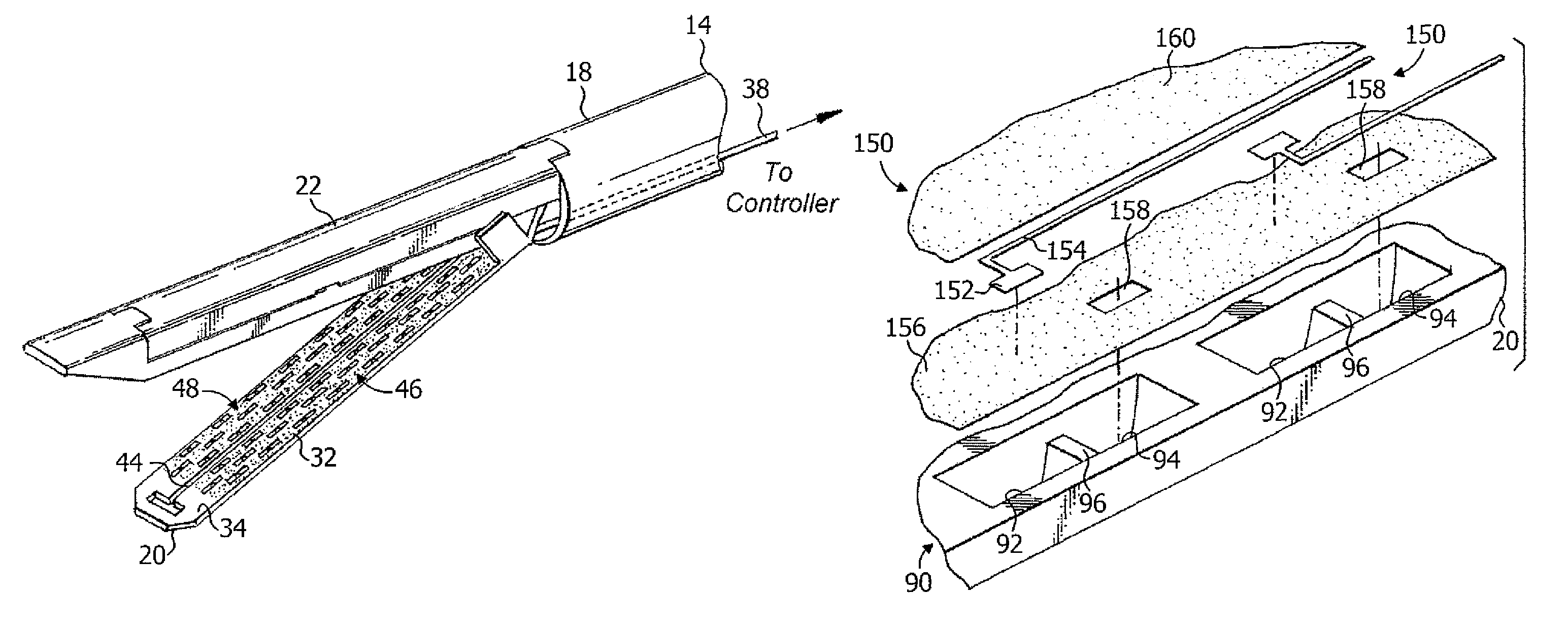
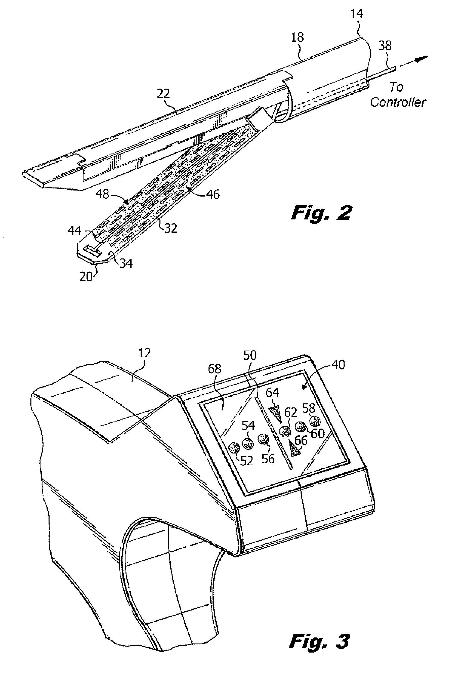
[0059]Referring initially to FIG. 1, there is disclosed a surgical stapler 10 having a handle portion 12 and an elongate tubular member 14 extending distally from handle portion 12. An end effector 16 is mounted on a distal end 18 of elongate tubular member 14 and generally includes an anvil member 20 and a staple cartridge 22. A proximal end 24 of staple cartridge 22 is removably attached to distal end 18 of elongate tubular member 14. Anvil member 20 is movably mounted relative to staple cartridge 22 such that anvil member 20...


PUM

PropertyMeasurementUnit
electrically resistiveaaaaaaaaaa
resistanceaaaaaaaaaa
inductanceaaaaaaaaaa

Abstract

There is provided a surgical stapler having a staple formation recognition system incorporated into an anvil member of the surgical stapler. In one series of embodiments, a trace system and controller form an open electrical circuit and a surgical staple acts as an electrical connector to complete an electrical circuit and confirm the proper formation of the surgical staple. In another series of embodiments, a trace system and a controller form a complete electrical circuit which is broken by engagement of a surgical staple with a trace pad of the trace system to signal proper formation of the surgical staple. There is also provided a knife blade position indication system for tracking the progress of a knife blade through the anvil member and relative to staple crimping pockets formed in the anvil member.

Description

CROSS REFERENCE TO RELATED APPLICATION[0001]The present application claims the benefit of and priority to U.S. Provisional Application Ser. No. 61 / 580,753, filed on Dec. 28, 2011, the entire contents of which are incorporated herein by reference.BACKGROUND[0002]1. Technical Field[0003]The present disclosure relates to an anvil member incorporating a staple formation recognition system for use with a surgical stapling instrument. More particularly, the present disclosure relates to an anvil member having a series of electrical traces positioned within staple forming pockets of the anvil member which detect the correct or incorrect formation of legs of a surgical staple within the staple forming pockets.[0004]2. Background of Related Art[0005]During various surgical procedures it is necessary to staple tissue with a surgical stapling instrument or surgical stapler to connect tissue sections or close off ends of tubular tissue sections permanently or temporarily to prevent leakage or p...

Claims


Application Information

Patent Timeline
Patent Type & Authority Patents(United States)
IPC IPC(8): A61B17/04A61B17/072A61B17/068A61B17/10A61B19/00A61B17/00A61B17/064
CPCA61B17/068A61B17/07207A61B17/0644A61B2019/4836A61B2017/00929A61B2017/07257A61B2017/07264A61B2017/0003A61B2090/0807
Inventor ZEMLOK, MICHAEL A.PRIBANIC, RUSSELLROSS, ADAM J.
Owner TYCO HEALTHCARE GRP LP
Learn More