
Auto-sensing hand dryer

a hand dryer and auto-sensing technology, applied in the field of auto-sensing hand dryers, can solve the problems of inconvenient use of hand dryers, insufficient sensing capability of infrared sensors, and paper towels that are disposed after one-time use that do not meet the green requirements of the world today

Active Publication Date: 2015-12-29
HOKWANG IND
View PDF19 Cites 6 Cited by
  • Summary
  • Abstract
  • Description
  • Claims
  • Application Information

AI Technical Summary

Benefits of technology

The present invention is an auto-sensing hand dryer that effectively senses a user's hands and provides a hand drying airflow. The guiding duct is used to guide the hand drying airflow and keeps the air discharge opening away from the airflow generating device. This ensures that the air flows smoothly and efficiently. The guiding duct can also be placed on a washbasin platform, allowing users to directly blow dry their hands after washing them. Overall, the invention improves the user's experience and provides a more convenient and comfortable drying experience.

Problems solved by technology

However, such paper towels that are disposed after one-time use do not meet green requirements of the world today.
When a user intuitively places hands near the airflow discharge opening, the infrared sensor offers inadequate sensing capability for sensing the hands of the user due to the abovementioned distance, in a way that the hand dryer is not driven and fails to provide a hand drying airflow.
Further, as the hands of the user need to move back and forth near the airflow discharge opening in order to drive the infrared sensor to perform the corresponding sensing operation, the usage such hand dryer is made quite inconvenient.

Method used


Image

  • Auto-sensing hand dryer
  • Auto-sensing hand dryer
  • Auto-sensing hand dryer

Examples


Embodiment Construction

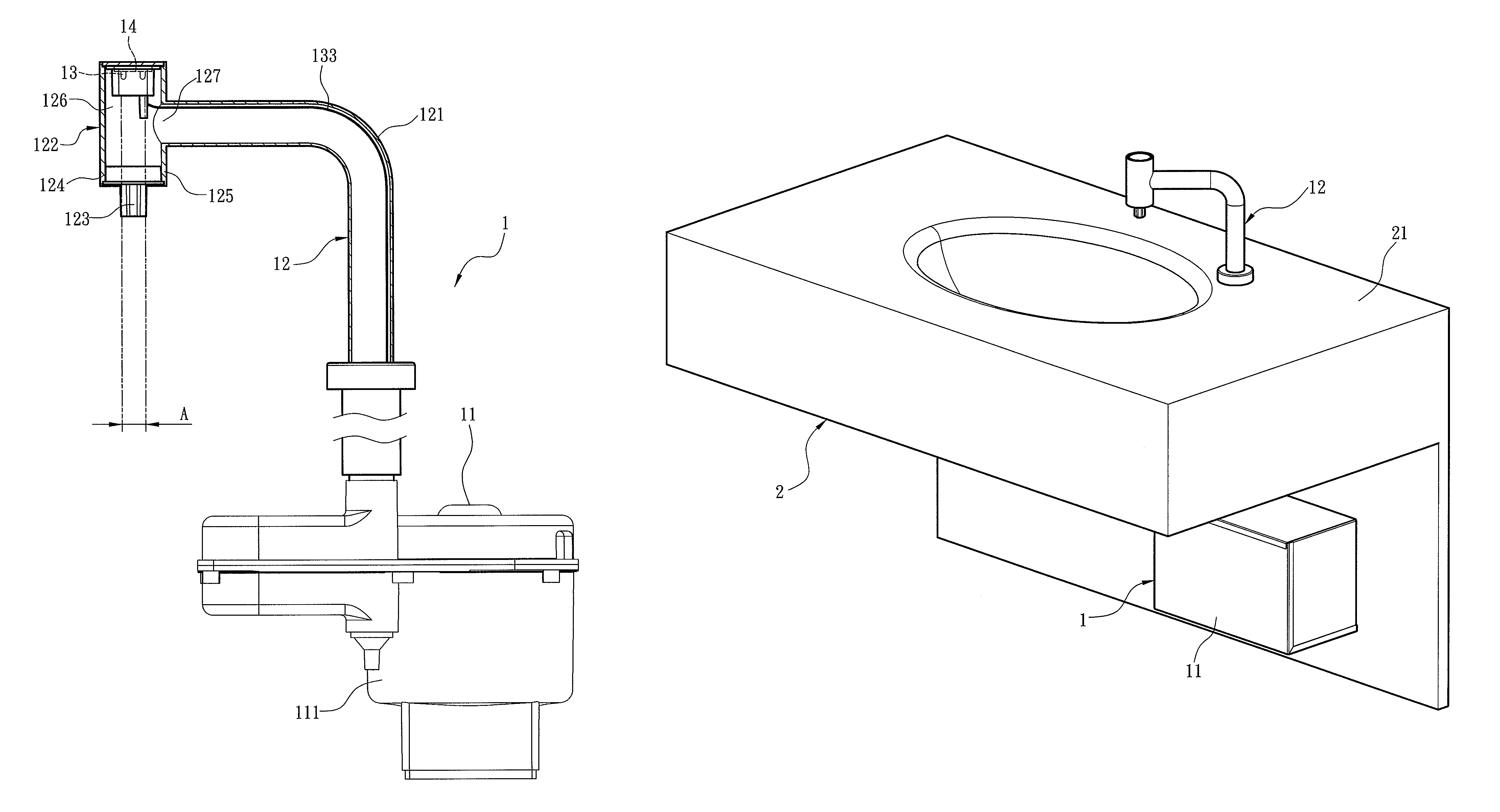
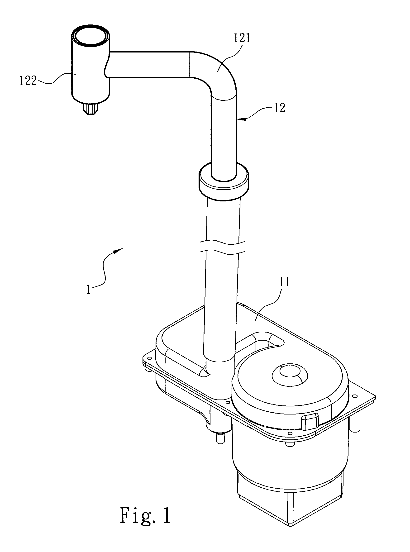
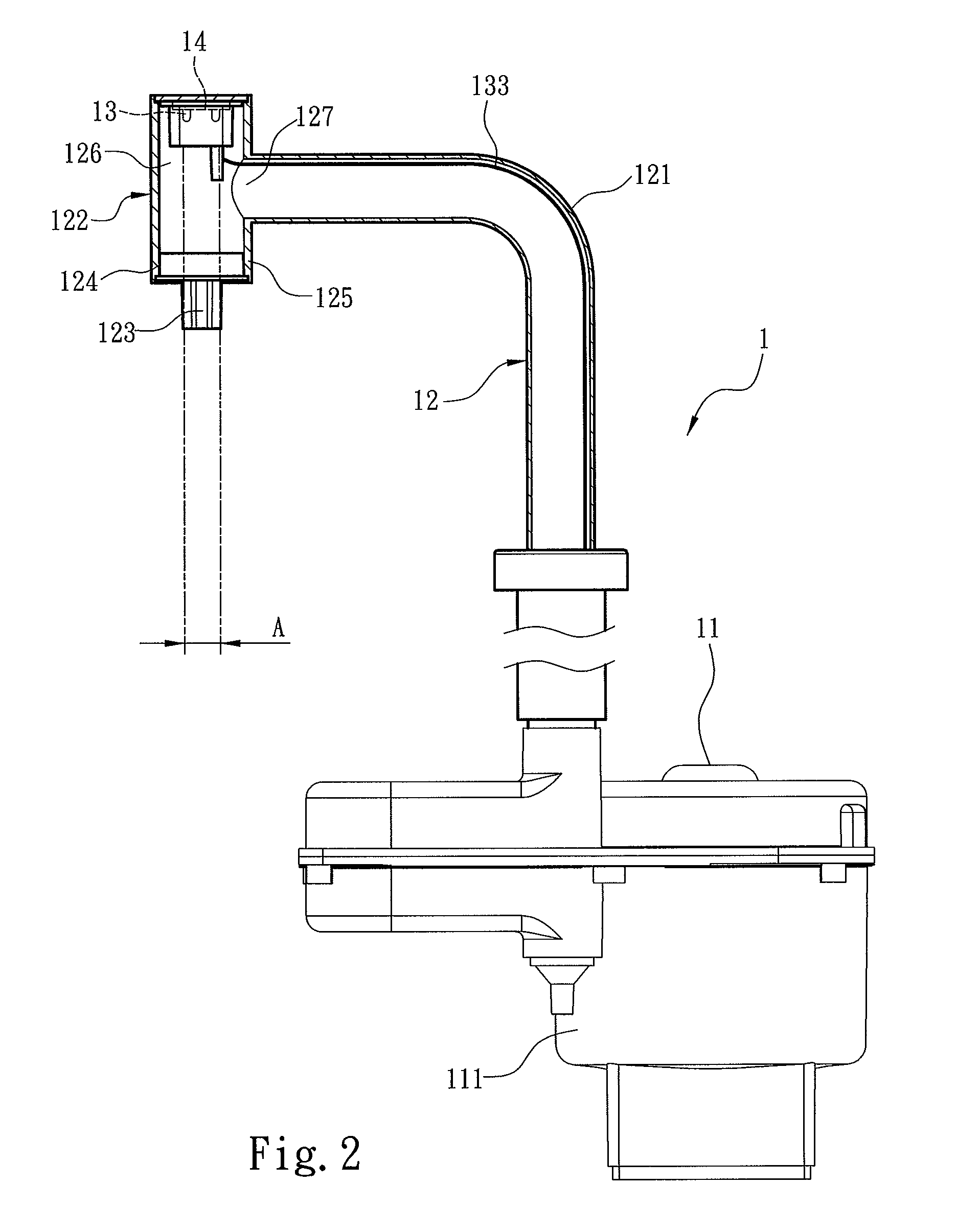
[0019]Referring to FIGS. 1 and 2, an auto-sensing hand dryer 1 of the present invention includes an airflow generating device 11, a guiding duct 12 connected to the airflow generating device 11, and a sensing unit 13 disposed in the guiding duct 12 and electrically connected to the airflow generating device 11. The airflow generating device 11 generates a hand drying airflow. The guiding duct 12 obtains the hand drying airflow from the airflow generating device 11 and guides a direction of the hand drying airflow. The sensing unit 13 detects a user hand to determine whether the airflow generating device 11 is to generate the hand drying airflow. Referring to FIG. 4, in the embodiment, the airflow generating device 11 of the auto-sensing hand dryer 1 is disposed below a washbasin 2, and the guiding duct 12 connected to the airflow generating device 11 may be connected to a platform 21 of the washbasin 2 from below the washbasin 2.

[0020]Referring to FIGS. 2 and 3, in the embodiment, t...


PUM


Abstract

An auto-sensing hand dryer includes an airflow generating device, a guiding duct connected to the airflow generating device, and a sensing unit disposed in the guiding duct. The airflow generating device generates a hand drying airflow. The guiding duct includes a connecting portion communicating with the airflow generating device, an air outlet portion communicating with the connecting portion. The air outlet portion comprises an air discharge opening and a housing encircling the air discharge opening and forming an internal space. The sensing unit is disposed in the internal space and electrically connected to the airflow generating device to determine whether to generate the hand drying airflow. The sensing unit includes a sensing region at least covering the air discharge opening. When a user hand is placed at the air discharge opening, the sensing unit senses the user hand and drives the airflow generating device to generate the hand drying airflow.

Description

FIELD OF THE INVENTION[0001]The present invention relates to an auto-sensing hand dryer, and particularly to an auto-sensing hand dryer including a sensing unit having a sensing region covering an air discharge opening of the auto-sensing hand dryer.BACKGROUND OF THE INVENTION[0002]Hygienics in the daily life continues to draw more attention as humanities improve. For one, hygienics is particularly valued in public restrooms. To quickly remove residual water from hands after washing hands, paper towels for wiping hands are usually offered in public restrooms. However, such paper towels that are disposed after one-time use do not meet green requirements of the world today. As a result, hand dryers that can be used to replace paper towels are widely provided in public restrooms.[0003]With the progress of infrared sensors, technologies for driving a hand dryer through sensing hands of a user by an infrared sensor have been developed. For example, the Taiwan Patent I326207 discloses “De...

Claims


Application Information

Patent Timeline
Patent Type & Authority Patents(United States)
IPC IPC(8): F26B21/12A47K10/48A47K10/36
CPCA47K10/48A47K2010/3668
Inventor LIU, SHEN-CHEN
Owner HOKWANG IND
Learn More