One motor finger mechanism

a finger mechanism and motor technology, applied in the field of motor finger mechanism, can solve the problems of undesirable curling behavior and the inability of the finger to curl around objects

Active Publication Date: 2015-12-15
HDT EXPEDITIONARY SYST INC
View PDF33 Cites 5 Cited by
  • Summary
  • Abstract
  • Description
  • Claims
  • Application Information

AI Technical Summary

Problems solved by technology

A kinematic mechanism produces consistent, predictable motion of the finger joints, but it does not allow the finger to curl around an object.
Differential mechanisms allow curling and grasping, but often deviate from the desired motion due to forces at the fingertip, causing buckling, or due to friction in the joints, causing undesirable curling behavior when not conforming.

Method used


Image

  • One motor finger mechanism
  • One motor finger mechanism
  • One motor finger mechanism

Examples


Embodiment Construction

[0024]In the following description of a mechanical finger, like numbers refer to like parts.

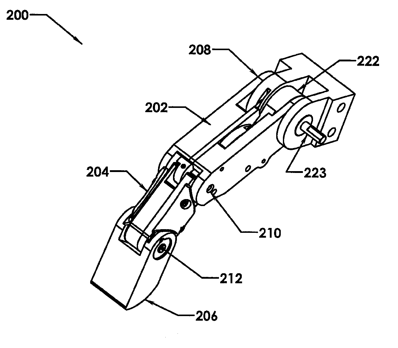
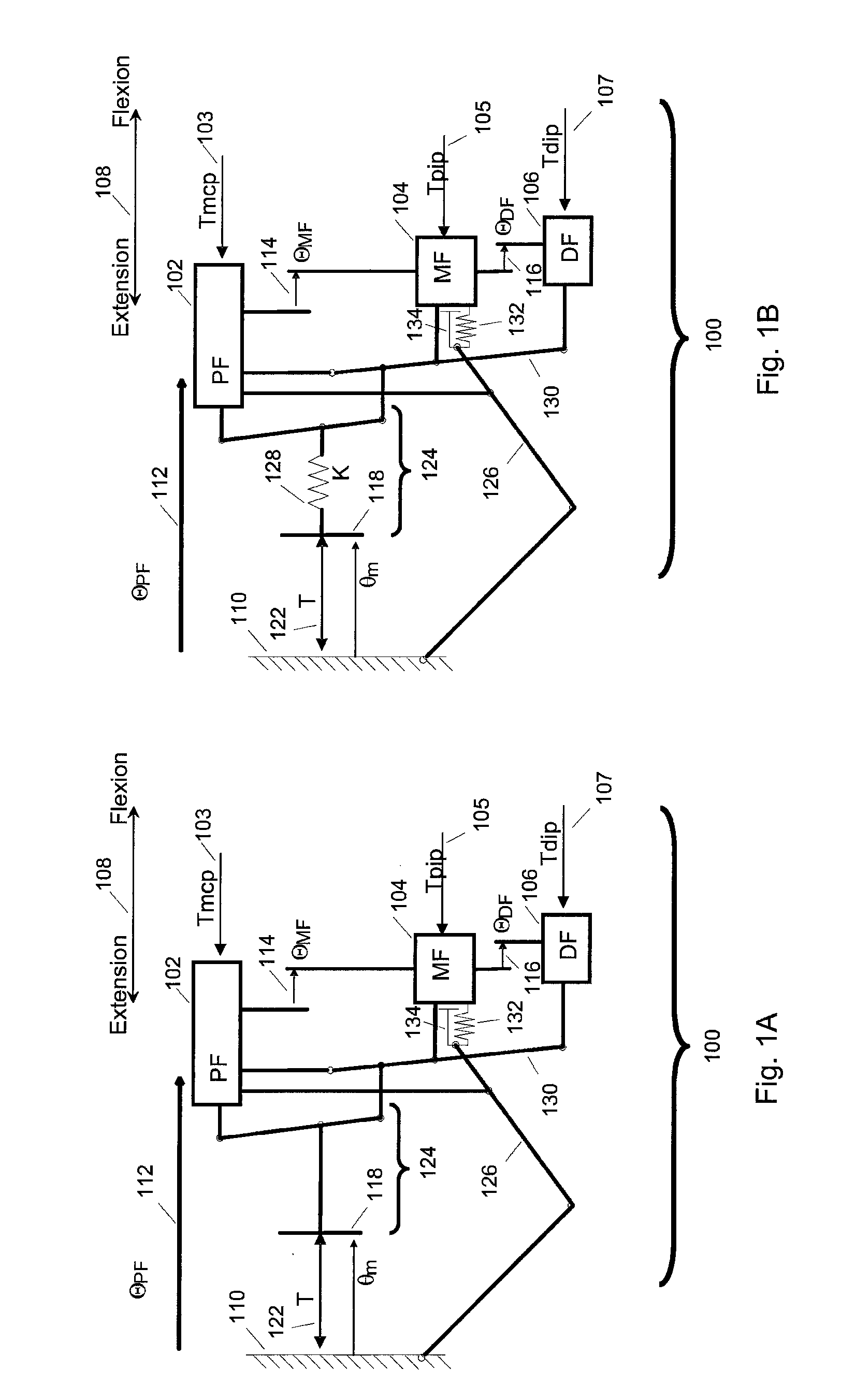
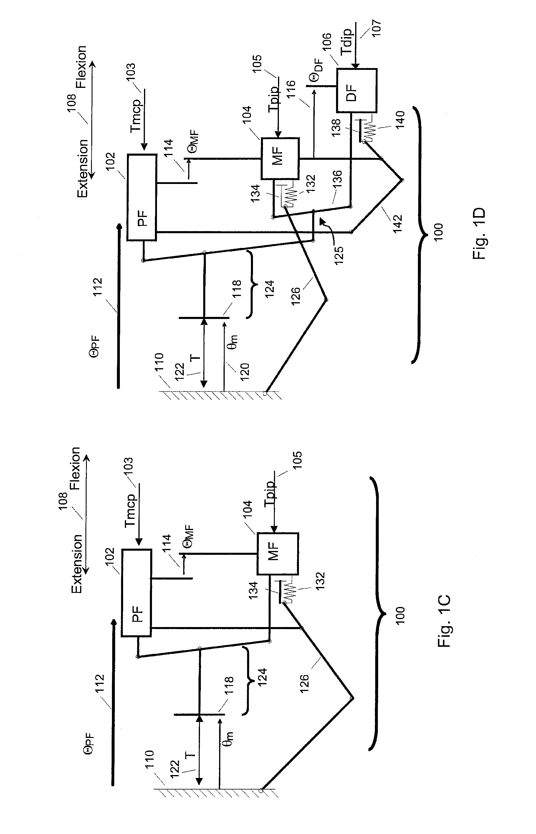
[0025]FIGS. 1A-1E schematically illustrate several alternative embodiments of mechanisms for driving a mechanical finger 100 using a single motor. The mechanism combines a differential, a kinematic linkage and a PIP linkage for coupling the torque and position of a drive output to a mechanical finger 100 having at least two sections in order to control its flexion and extension in a manner that permits it to be used in connection with grasping or other applications in which a curling action is desirable. Such applications include, but are not limited to, robotic hands and prosthetic hands.

[0026]The illustrated examples of mechanical finger 100 comprise at least a proximal phalanx 102, a medial or middle phalanx 104, and, in the embodiments of FIGS. 1A to 1E, a distal phalanx 106. “Phalanx” refers to an elongated, rigid section of the finger, and “phalanges” to multiple sections of the finger....


PUM


Abstract

A mechanical finger comprises a plurality of phalanges coupled to a single actuator using a kinematic linkage and a differential linkage arranged in parallel. The mechanical finger is capable of exhibiting consistent predictable motion when moving in free space or when contacting an object at the fingertip, and of curling in order to conform to an object when the contact is at other locations on the finger.

Description

CROSS REFERENCE TO RELATED APPLICATIONS[0001]This application is a continuation of U.S. application Ser. No. 12 / 965,362 filed Dec. 10, 2010, now assigned U.S. Pat. No. 8,470,051, which claims priority from and benefit of the filing date of U.S. provisional application Ser. No. 61 / 286,345 filed Dec. 14, 2009, and the entire disclosure of each of said prior applications is hereby expressly incorporated by reference into the present specification.GOVERNMENT INTEREST[0002]This invention was made with government support under Contract No. N66001-06-C8005, awarded by Defense Advanced Research Projects Agency. The government has certain rights in the invention.BACKGROUND[0003]A “mechanical finger” refers to an elongated, articulating, mechanical appendage. Like a human finger, a mechanical finger has one end joined to a structure that acts as a base and an opposite end that is not anchored or connected. A mechanical finger used for grasping typically has two or more rigid sections, and pre...

Claims


Application Information

Patent Timeline
Patent Type & Authority Patents(United States)
IPC IPC(8): A61F2/58A61F2/50
CPCA61F2/586A61F2002/5072
Inventor MOYER, THOMASFAULRING, ERIC L.SANTOS-MUNNE, JULIO J.
Owner HDT EXPEDITIONARY SYST INC
Why Eureka
Try Eureka