
Quick assembly methods and components for shade structures

a technology of shade structure and assembly method, applied in the direction of walking sticks, etc., can solve the problems of unable to bear a full range of operational loads, insufficient devices, and high manufacturing costs, and achieve the effect of preventing the pull of the umbrella rib

Active Publication Date: 2015-11-24
OLIVER JOEN AN MA
View PDF106 Cites 37 Cited by
  • Summary
  • Abstract
  • Description
  • Claims
  • Application Information

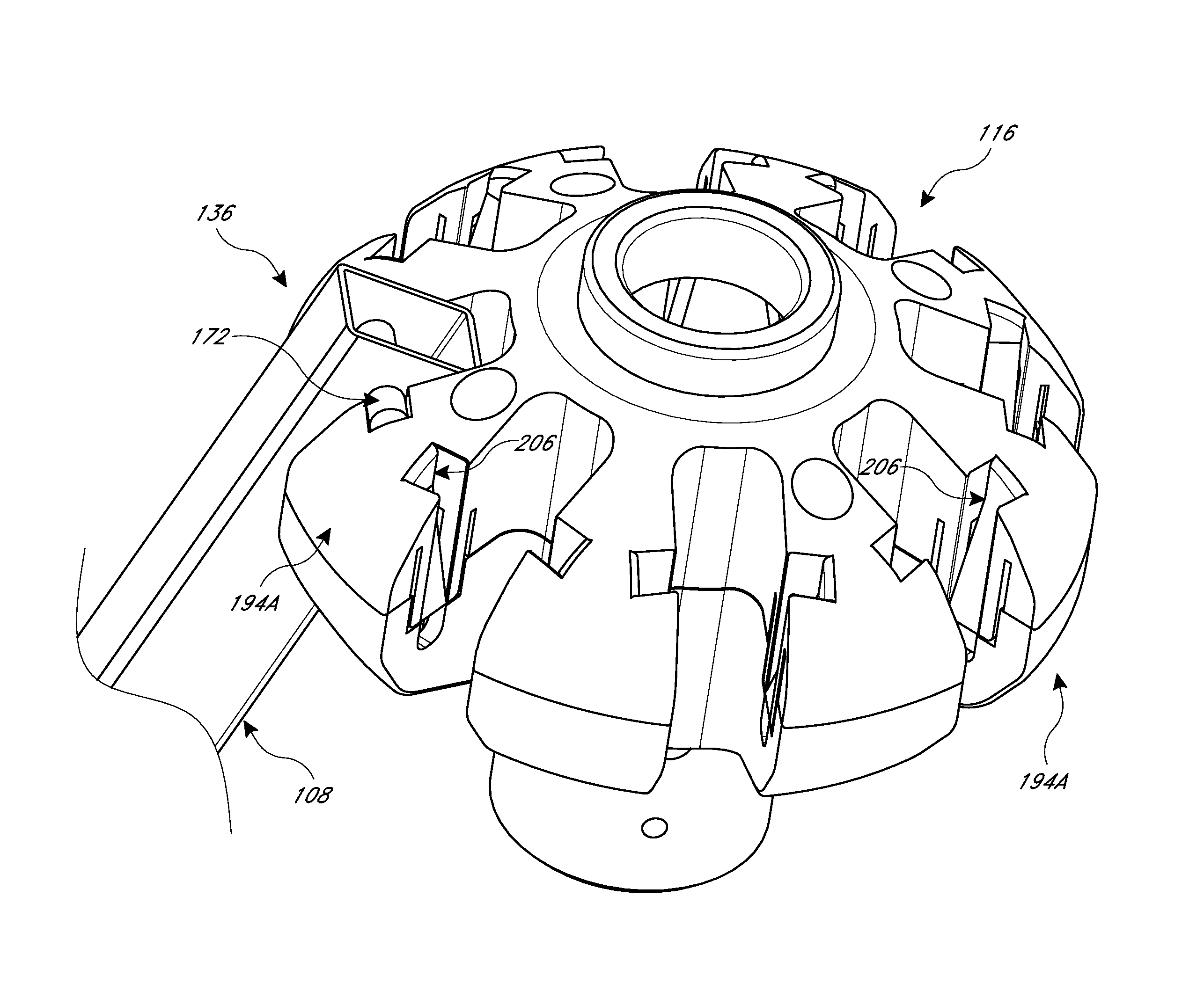
AI Technical Summary

Benefits of technology

[0006]It would be beneficial to provide structures that enable quicker and less labor intensive assembly of umbrella assemblies, e.g., rib and hub assemblies. An aspect of at least one of the embodiments disclosed herein is the realization that the connection devices used in the assembly of shade structures, such as pavilions and outdoor umbrellas, can be improved to provide a more secure, quicker, and more reliable connection. Such devices can use fewer parts and be easier to manufacture than those devices of the prior art. Such improved connections can be particularly advantageous for large shade structures.
[0007]According to another aspect of at least one embodiment disclosed herein is the realization that prior art umbrella hubs include an excessive amount of individual components. For example, individual pins are often individually placed into a portion of the hub before portions of the hub are carefully assembled. This tedious manufacturing can be costly and frustrating. Therefore, embodiments disclosed herein seek to remedy this deficiency by providing a hub assembly that uses a reduced number of parts. Accordingly, the time and cost required for manufacturing the hub can be greatly decreased.
[0011]In another aspect, an umbrella hub is provided that includes a central portion and a body. The central portion is configured to receive to an umbrella pole. The body has a top surface and a bottom surface extending between the central portion and an outer periphery of the hub. An outer portion disposed adjacent to the outer periphery is configured to receive an end portion of an umbrella structural member. The hub also includes a retention mechanism disposed within the outer portion of the body. The retention mechanism includes a channel and a moveable retention device. The channel extends from an opening at the top surface toward the bottom surface. The moveable retention device is disposed between the opening and the bottom surface. A first configuration of the moveable retention device permits an umbrella structural member to be moved from the opening of the channel to a retained position. A second configuration the moveable retention device prevents the umbrella structural member from being withdrawn from the retention mechanism.
[0013]In other broad aspects, a downward movement of a pin can actuate a retention device from a blocking configuration to an assembly configuration. The retention device can return to a blocking configuration by releasing stored strain energy. These configurations may provide for a simple downward movement to actuate a retention mechanism out of the blocking configuration and to permit the retention mechanism to return to the blocking configuration. As used herein, downward can refer to vertically from a higher elevation to a lower elevation and also can mean generally away from a top surface of a hub toward a bottom surface of the hub regardless of the orientation of the hub.
[0015]Various innovative methods of manufacture also arise from the disclosure herein. In particular, a hub can be assembled using a guide pin and guide recess arrangement. These features quickly and accurately line up holes that receive conventional fasteners. As such assembly of an umbrella hub or a full umbrella assembly can be much more rapid and efficient.
[0017]In another embodiment, a method of assembling umbrella components is provided. In the method, an umbrella pole and an umbrella hub are provided. The umbrella pole is disposed within the umbrella hub. An umbrella rib having an inner end is disposed above a slot of the hub. A shaft of the rib end is aligned with a vertical channel of the hub. The shaft is moved relative to the hub from the top surface of the hub toward the bottom surface of the hub. The shaft is secured within the umbrella hub permitting rotation of the umbrella rib while preventing withdrawal of the umbrella rib.

Problems solved by technology

This tedious manufacturing can be costly and frustrating.
Another aspect of at least one of the embodiments disclosed herein is the realization that while some devices to expedite assembly have been suggested, such devices have been inadequate, for example lacking the ability to bear a full range of operational loads, which can be much higher than the weight of the components of the shade structure, particularly in windy conditions.

Method used


Image

  • Quick assembly methods and components for shade structures
  • Quick assembly methods and components for shade structures
  • Quick assembly methods and components for shade structures

Examples


Embodiment Construction

[0036]In accordance with embodiments described herein, there are provided various configurations of a hub and hub assembly that can be used with an umbrella support structure, such as an umbrella or pavilion, to facilitate the rapid and secure fastening of structural ribs with a hub or other structure. As described in greater detail herein, the hub and hub assembly can incorporate various features such that a secure connection with a structure, such as a mounting member of a hub of an umbrella, can be obtained. Additional details and features of related umbrella rib connectors and assemblies are illustrated and described in Applicant's U.S. Pat. No. 7,703,464, issued Apr. 27, 2010, entitled and in Applicant's U.S. Pat. No. 7,891,367, issued Feb. 22, 2011, entitled the entirety of the contents of both of which are incorporated herein by reference.

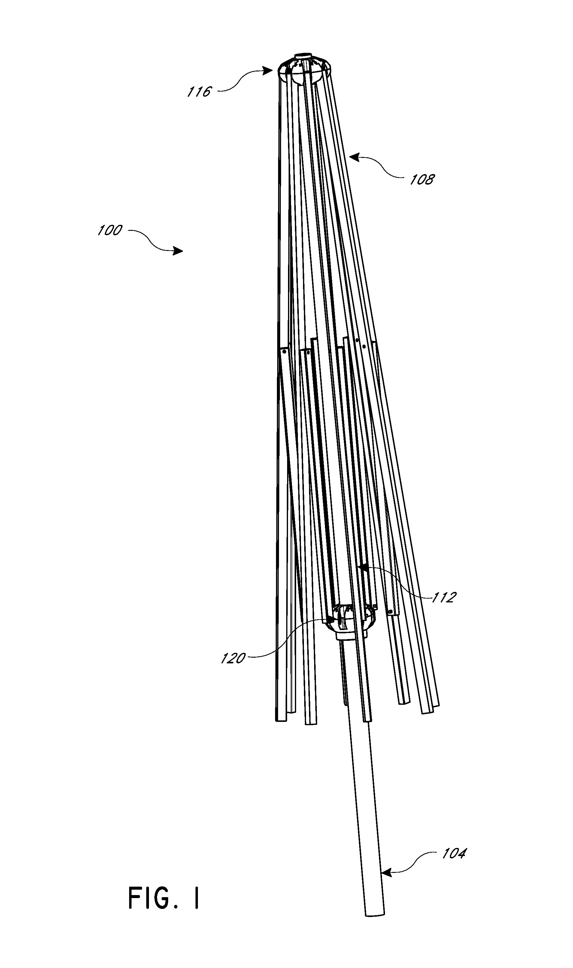
[0037]FIG. 1 shows an umbrella assembly 100 that is large in size, such as for a patio or market space to provide shade to a table or other...


PUM

PropertyMeasurementUnit
distanceaaaaaaaaaa
elevationaaaaaaaaaa
rotationaaaaaaaaaa

Abstract

A quick connect system is provided for a shade structure. The system includes a hub and a structural member. The hub has a top surface, a plurality of side walls forming a slot therebetween, and a displaceable retention device having a free end disposed at an elevation below the top surface. The displaceable retention device is moveable laterally away from the slot. The structural member has an end configured to swing in the slot. The end has a laterally extending rotation device. The rotation device extends laterally beyond the free end of the displaceable retention device when the end is disposed in the slot.

Description

BACKGROUND OF THE INVENTIONS[0001]1. Field of the Invention[0002]This application relates to apparatuses and methods that facilitate efficient assembly of ribs and hubs of umbrellas and other structures with a plurality of arms that extend from a central hub member.[0003]2. Description of the Related Art[0004]Larger umbrellas, such as market umbrellas, generally include a frame-like structure that is used to support and distribute the weight of an upper portion of the umbrella as well as to enable the umbrella to be opened and closed as desired by the user. The frame-like structure of such umbrellas can take various forms, but often includes one more hubs connected with a plurality of movable structural members.[0005]Past methods of assembly of umbrella hubs and ribs was labor intensive. The process involved inserting a pin through an end portion of a set of ribs, positioning all of the rib ends in a lower portion of a hub, and then placing an upper portion of the hub over the ribs ...

Claims


Application Information

Patent Timeline
Patent Type & Authority Patents(United States)
IPC IPC(8): A45B25/06A45B25/10A45B25/00
CPCA45B25/10A45B25/00A45B25/06Y10T29/40
Inventor MA, OLIVER JOEN-AN
Owner OLIVER JOEN AN MA
Learn More