
Systems and methods for flow sensing in a conduit

a flow sensing and conduit technology, applied in the direction of instruments, heat measurement, volume metering, etc., can solve the problems of insufficient responsiveness of conventional systems to these different factors, inaccurate readings, and poor robustness of conventional systems

Inactive Publication Date: 2015-10-27
AMPHENOL THERMOMETRICS
View PDF15 Cites 3 Cited by
  • Summary
  • Abstract
  • Description
  • Claims
  • Application Information

AI Technical Summary

Benefits of technology

The patent text describes a fluid flow sensor assembly and method for accurately measuring the flow rate of fluid in a flow conduit. The assembly includes a flow disturber that creates flow disturbances in the fluid, which is then detected by a plurality of flow sensors. A frequency resolver is used to determine frequency information from the flow sensors based on the flow characteristics, which is then used to determine the flow rate of the fluid. The method allows for accurate and consistent flow rate measurement in a variety of situations.

Problems solved by technology

Some conventional systems are not satisfactorily responsive to these different factors.
As a result, the outputs of these systems may drift and cause readings that are not accurate.
Additionally, the robustness of these systems suffer.
Users of ventilation and / or respiratory machines may unilaterally decide to cease use of the machine as a result of the machine being uncomfortable during operation, such as when an appropriate air pressure is not supplied.
However, due to the complex nature of breathing and the change in direction and speed of air flow during breathing (as well as other factors), it is very difficult to determine flow rates.

Method used


Image

  • Systems and methods for flow sensing in a conduit
  • Systems and methods for flow sensing in a conduit
  • Systems and methods for flow sensing in a conduit

Examples


Embodiment Construction

[0015]The following detailed description of certain embodiments will be better understood when read in conjunction with the appended drawings. As used herein, an element or step recited in the singular and proceeded with the word “a” or “an” should be understood as not excluding plural of said elements or steps, unless such exclusion is explicitly stated. Furthermore, references to “one embodiment” are not intended to be interpreted as excluding the existence of additional embodiments that also incorporate the recited features. Moreover, unless explicitly stated to the contrary, embodiments “comprising” or “having” an element or a plurality of elements having a particular property may include additional elements not having that property.

[0016]Although the various embodiments may be described herein within a particular operating environment, it should be appreciated that one or more embodiments are equally applicable for use with other configurations and systems. Thus, for example, t...


PUM

PropertyMeasurementUnit
frequencyaaaaaaaaaa
frequencyaaaaaaaaaa
frequencyaaaaaaaaaa

Abstract

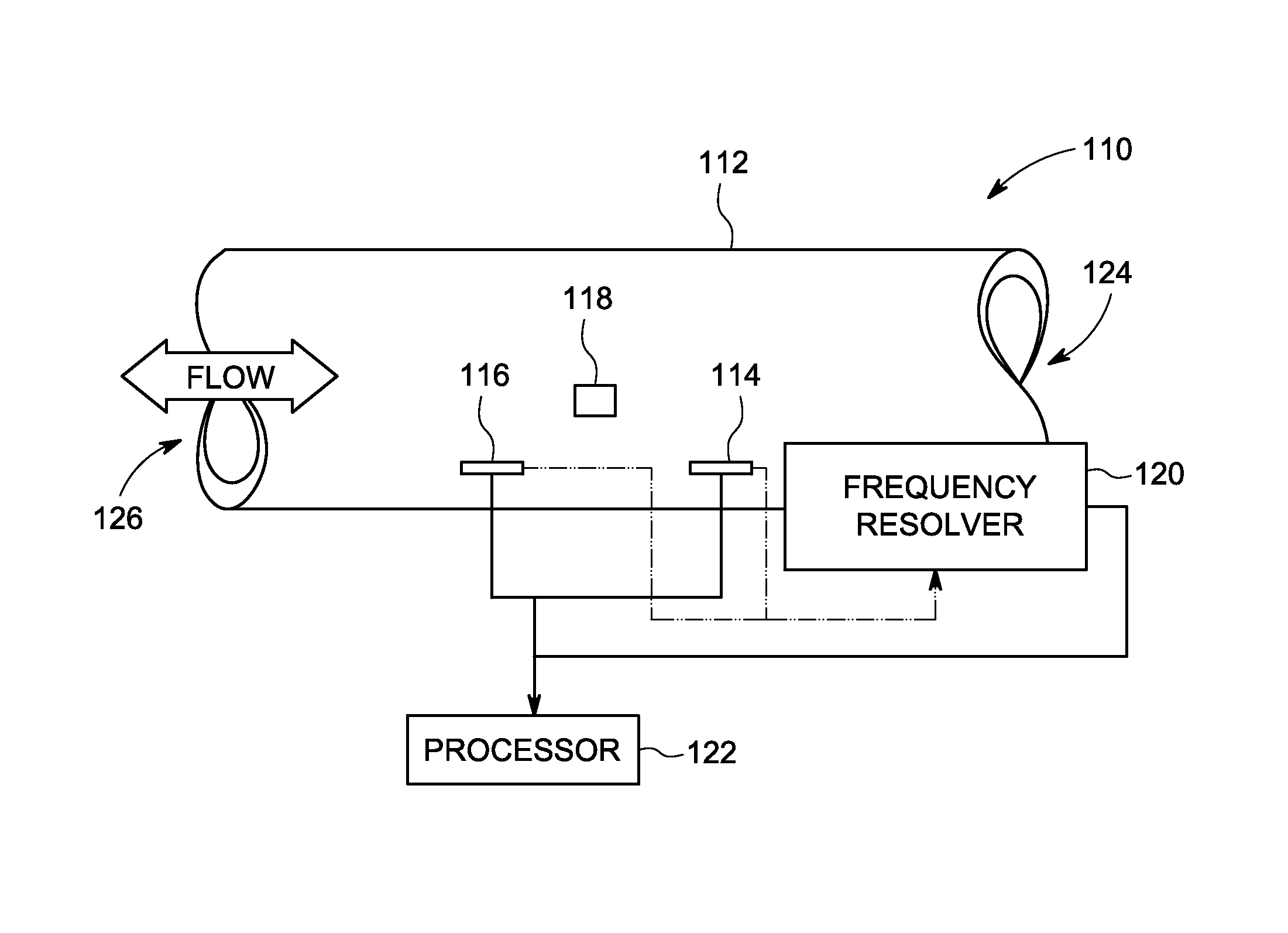
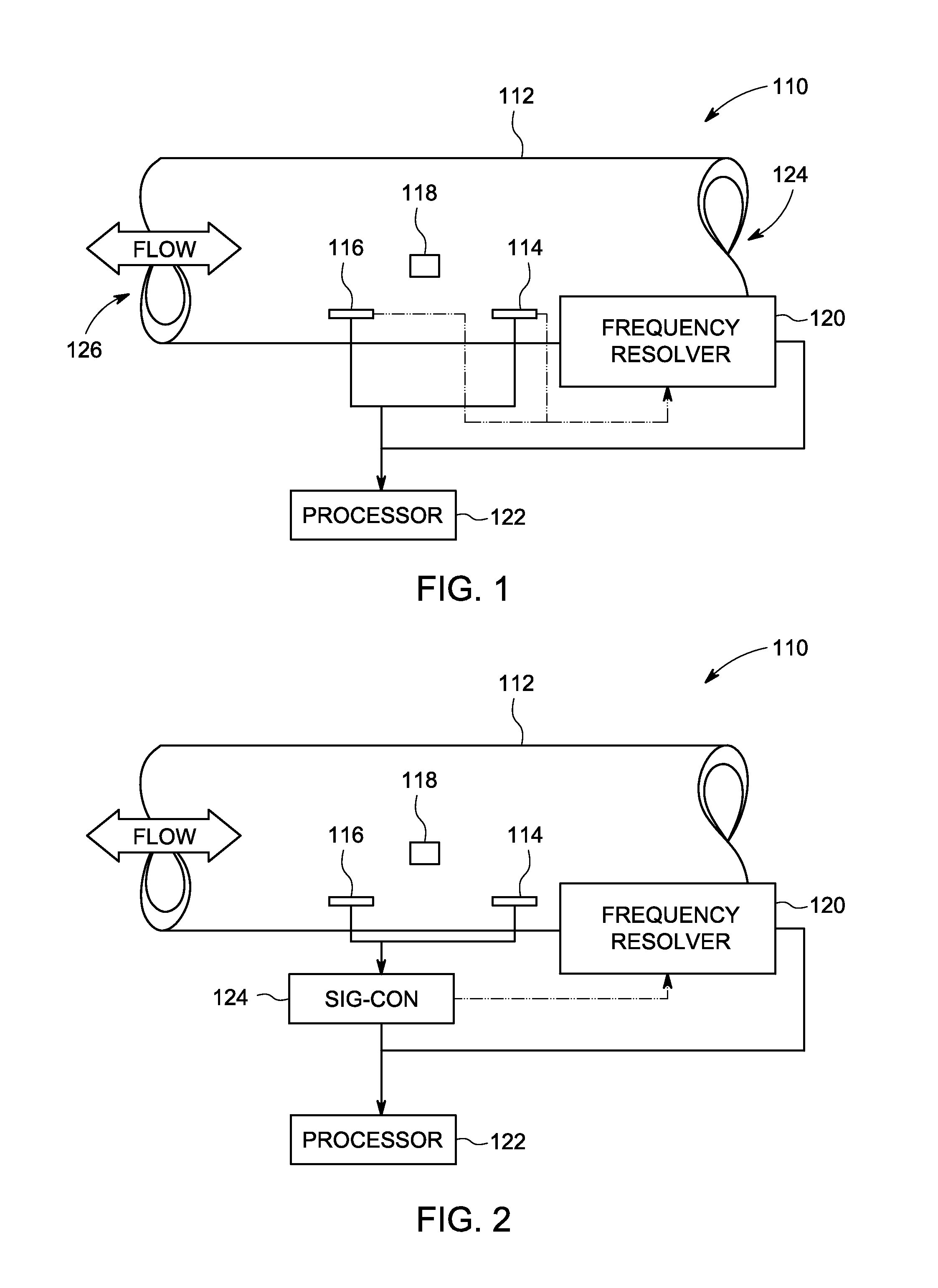
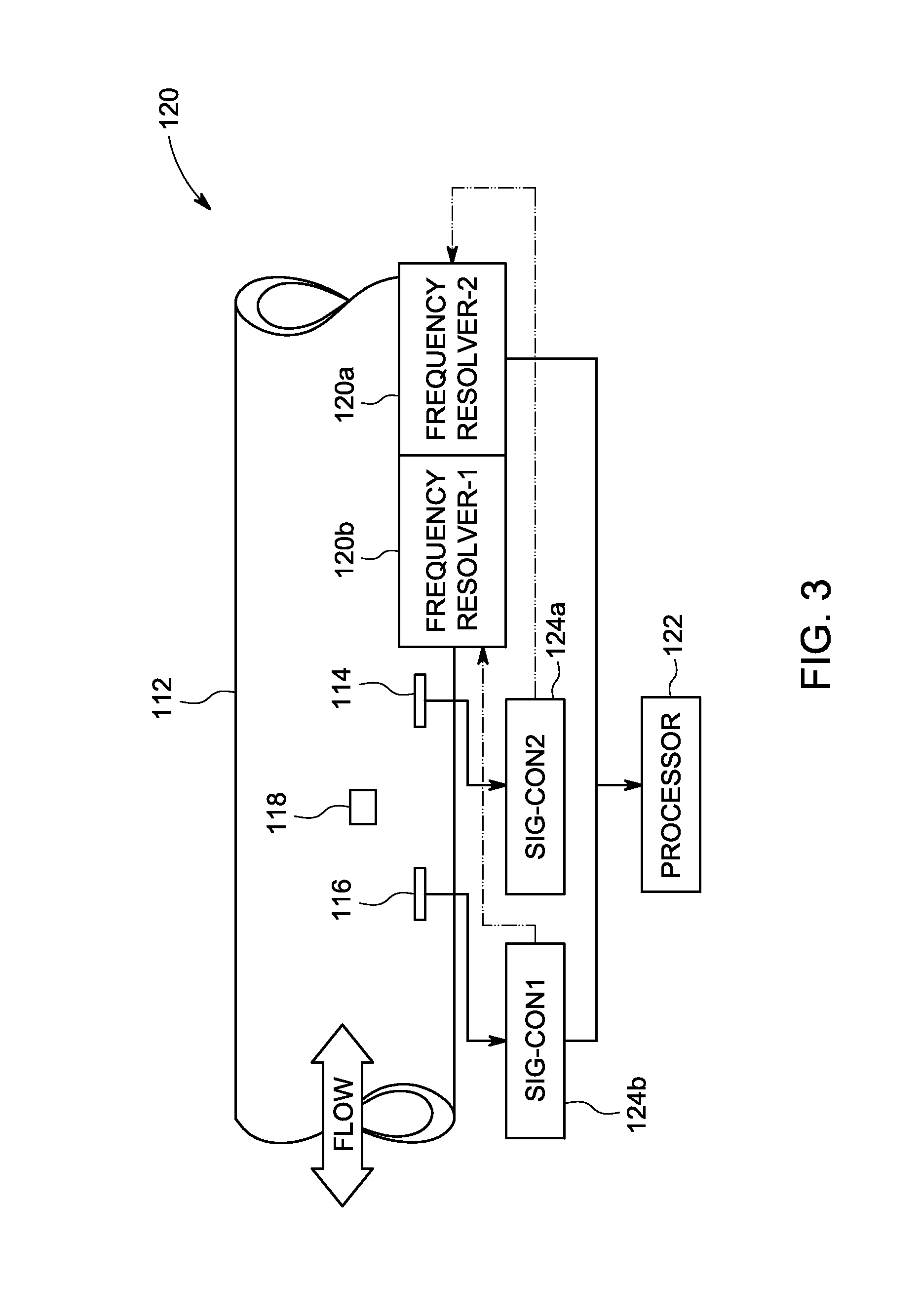
Systems and methods for flow sensing in a conduit are provided. One system includes a flow disturber disposed in a flow conduit and configured to impart a flow disturbance to the fluid flow. The system further includes a plurality of flow sensors disposed in the flow conduit and responsive to flow characteristics in the flow conduit. The system also includes a frequency resolver configured to determine frequency information related to the fluid flow based on the flow characteristics. The frequency resolver uses one or more time sample windows to select data samples for use in determining the frequency information, wherein a length of one or more of the time sample windows is based at least in part on the flow characteristics. The system additionally includes a processor configured to determine a flow rate of the fluid flow in the flow conduit using the frequency information.

Description

BACKGROUND[0001]Flow sensing may be used in a variety of different applications, such as to determine flow velocity of a fluid, such as gas (e.g., air) or liquid, through a pipe or tube. For example, flow sensing may be used in ventilation and respiration machines to detect and control the level of air flow. As another example, flow sensing may be used in gas metering systems, such as for residential applications.[0002]The determination of the fluid flow may be affected by many different factors, such as temperature, moisture variations, or the type or density of fluid, among others. Some conventional systems are not satisfactorily responsive to these different factors. As a result, the outputs of these systems may drift and cause readings that are not accurate. Additionally, the robustness of these systems suffer.[0003]In a medical setting, when using ventilation and respiration machines such as continuous positive airway pressure (CPAP) machine and a variable positive airway press...

Claims


Application Information

Patent Timeline
Patent Type & Authority Patents(United States)
IPC IPC(8): G01F1/00G01F1/32H02P23/00H03M1/04G01K1/00G01F25/00G01F15/02
CPCG01F1/32G01F1/3209G01K1/00G01F15/024G01F25/0007G01K13/02G01F25/10
Inventor BERKCAN, ERTUGRULKOUADA, IBRAHIM I.KLITZKE, MICHAELCHEN, NANNAN
Owner AMPHENOL THERMOMETRICS
Learn More