
Magnetically coupled solar-powered lights

a solar power and solar panel technology, applied in the field of solar power systems, can solve the problems of not being able to easily transfer light fixtures and solar panels are not even portable, and cannot be easily transferred to other outdoor gear such as tents, etc., and achieve the effect of easy transfer and light weigh

Inactive Publication Date: 2015-09-29
IP POWER HLDG
View PDF13 Cites 5 Cited by
  • Summary
  • Abstract
  • Description
  • Claims
  • Application Information

AI Technical Summary

Benefits of technology

The system allows for portable and lightweight solar lighting that can be easily transferred and securely fixed on different outdoor gear, providing reliable illumination by converting solar energy into battery power using magnetic alignment and electrode penetration.

Problems solved by technology

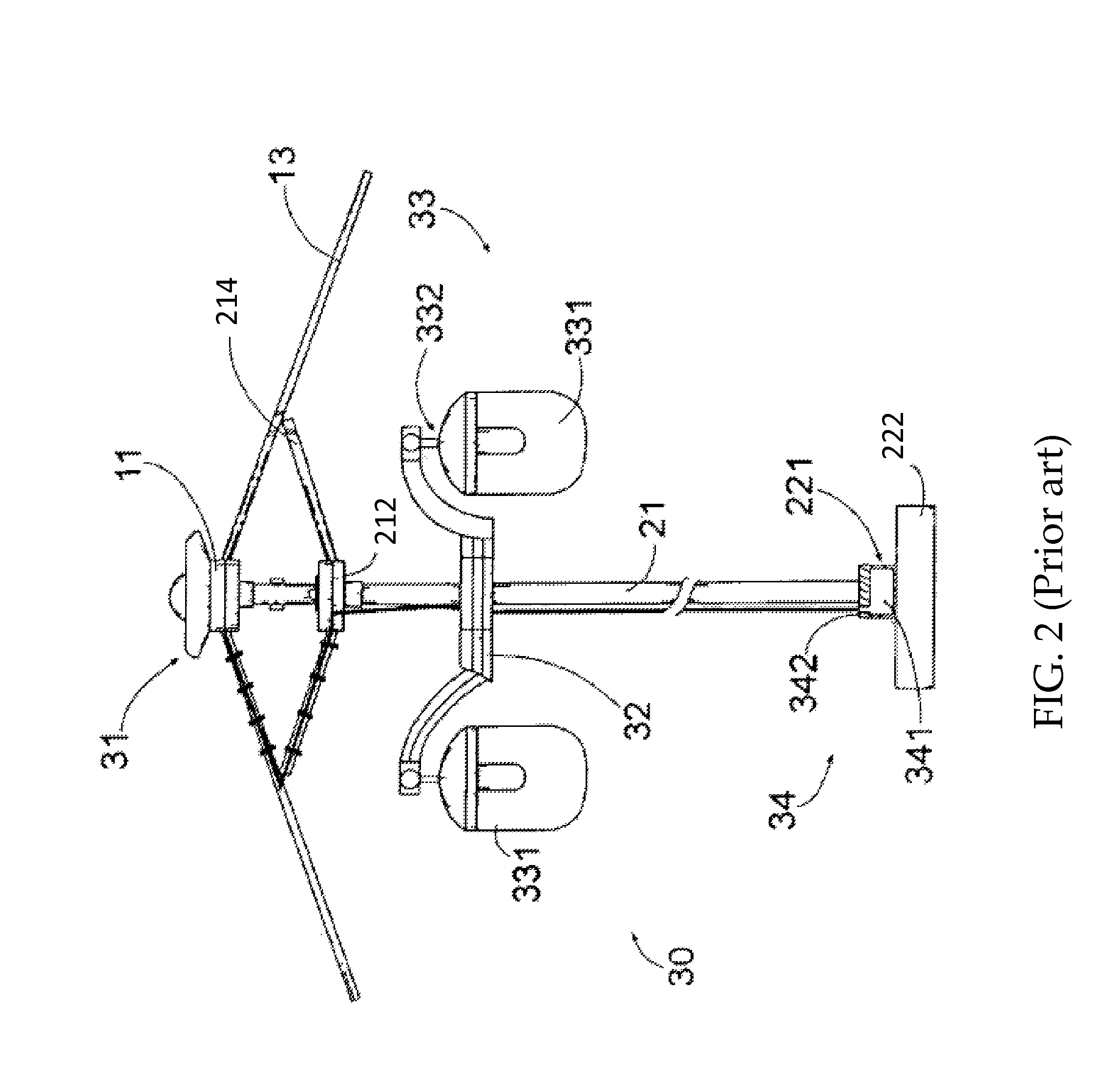
Even though the lighting fixture of the illuminated umbrella assembly is movable, the movement thereof is very limited because the solar panel is fixed on the umbrella assembly, and the connection and wiring between the solar panel and lighting fixture are fixed on the umbrella assembly.
In other words, the lighting fixture and the solar panel are not portable and cannot be easily transferred to other outdoor gears such as other outdoor umbrellas or tents.
However, the solar panels are fixed on the umbrella as well as the lighting fixtures, so the lighting fixture and the solar panel are not even portable and cannot be easily transferred to other outdoor gears such as tents.
Even though Ma mentions that the lighting device is portable, the lighting fixtures along with the solar panels are too bulky to carry, let alone transferring them to other outdoor gears.

Method used


Image

  • Magnetically coupled solar-powered lights
  • Magnetically coupled solar-powered lights
  • Magnetically coupled solar-powered lights

Examples


Embodiment Construction

[0023]The detailed description set forth below is intended as a description of the presently exemplary device provided in accordance with aspects of the present invention and is not intended to represent the only forms in which the present invention may be prepared or utilized. It is to be understood, rather, that the same or equivalent functions and components may be accomplished by different embodiments that are also intended to be encompassed within the spirit and scope of the invention.

[0024]Unless defined otherwise, all technical and scientific terms used herein have the same meaning as commonly understood to one of ordinary skill in the art to which this invention belongs. Although any methods, devices and materials similar or equivalent to those described can be used in the practice or testing of the invention, the exemplary methods, devices and materials are now described.

[0025]All publications mentioned are incorporated by reference for the purpose of describing and disclos...


PUM

PropertyMeasurementUnit
magnetic forceaaaaaaaaaa
energyaaaaaaaaaa
solar energyaaaaaaaaaa

Abstract

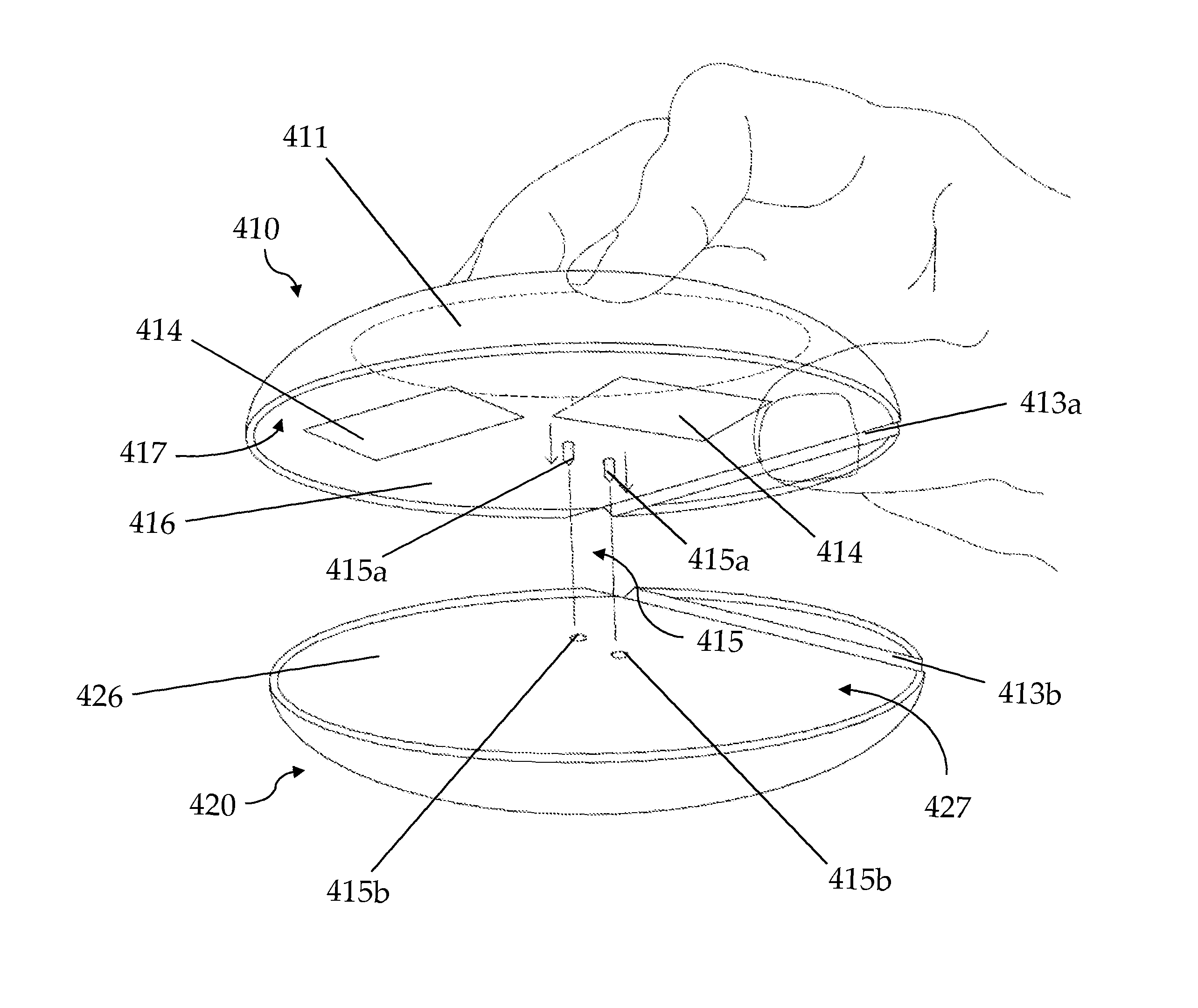
A solar lighting apparatus includes a controlling portion, having a first conjugating surface, a button with a plurality of lights, and electrodes hidden in the controlling portion; and an energy collecting portion, having a second conjugating surface, a solar panel to absorb sunlight, and corresponding receiving holes to receive the electrodes of the controlling portion, wherein a magnetic force is generated between the controlling portion and the energy collecting portion to tightly bind these two portions, and the electrodes are attracted out from the controlling portion by the magnetic force to plug into the receiving holes to form an energy conversion circuit to convert solar energy collected by the solar panel to other forms of energy.

Description

FIELD OF THE INVENTION[0001]The present invention relates to solar-powered lights, and more particularly to a solar lighting system that is portable and can be secured at outdoor gears such as outdoor umbrellas and tents.BACKGROUND OF THE INVENTION[0002]Recently, solar energy becomes more and more popular to convert sunlight into other types of energy such as electricity and heat. Solar power is advantageous in situations where other power sources are unavailable because solar energy can be collected during the daytime via solar panels and the collected energy can be used to power other devices during the nighttime. In some situations, the solar cell can directly power a device, but it is more common to have the solar cell charged and maintain an energy storage device.[0003]An LED (light-emitting diodes) lamp is a type of solid-state lighting that utilizes LEDs as a source of illumination. Recently, the use of LEDs for various lighting purposes has increased because LEDs have a very...

Claims


Application Information

Patent Timeline
Patent Type & Authority Patents(United States)
IPC IPC(8): A45B3/04F21L4/08F21V17/10F21S9/03F21Y101/02
CPCF21L4/08F21S9/032F21V17/105F21Y2101/02Y10T29/49117F21Y2115/10
Inventor ZHU, SHOU QIANG
Owner IP POWER HLDG
Learn More