Integrated thermal module and back plate structure and related methods

a thermal module and back plate technology, applied in the direction of heat collector mounting/support, thermal-pv hybrid energy generation, lighting and heating apparatus, etc., can solve the problems of not being able to compete with the direct purchase of electricity from public power companies, solar cells are often costly, and still certain limitations, so as to improve the operation procedure of solar modules and facilitate use. , the effect of improving the operation procedur

Inactive Publication Date: 2015-08-11
SUNEDISON INC
View PDF118 Cites 10 Cited by
  • Summary
  • Abstract
  • Description
  • Claims
  • Application Information

AI Technical Summary

Benefits of technology

[0018]In a specific embodiment, the present invention provides a thermal solar system having a fire resistant characteristic. The system includes a solar module having an aperture region and a backside region. The system has a shaped thickness of material having a first side and a second side. In a specific embodiment, the shaped thickness of material is characterized by a fire resistant characteristic including a thickness to be free from penetration of moisture. In a specific embodiment, the thickness of material has a structural characteristic capable of maintaining a shape and coupling to the backside region of the thermal solar module. The system also has an air plenum provided between the thermal solar module and the thickness shaped thickness of material and a frame assembly operably coupled to the shaped thickness of material to support the shaped thickness of material and the thermal solar module. The system also has a building structure holding the frame assembly. In a preferred embodiment, the building structure has an inner region having a first pressure. In one or more embodiments, the inner region can be an attic region or other inner building region or regions. In a specific embodiment, the system has a second pressure characterizing the air plenum. In a specific embodiment, the second pressure is equal to or less than the first pressure to cause a dynamic pressure on the solar module to be directed through the air plenum. In a preferred embodiment, the second pressure maintains the inner region of the building structure substantially free from water driven from the dynamic pressure during rain fall or wind.
[0019]Many benefits are achieved by way of the present invention over conventional techniques. For example, the present technique provides an easy to use process that relies upon conventional technologies such as thermal solar modules and drive devices, although other elements can also be used. Additionally, the method provides a process that is compatible with the instant thermal solar system without substantial modifications to equipment and processes. Preferably, the invention provides for an improved solar module operation procedure, which is less costly and easy to handle. Such solar module operation system uses a shaped material or structure in the form of a pan, which is configured underlying a solar array, including its components, and integral with a rack structure according to one or more embodiments. In a preferred embodiment, the pan structure can be composed of a plurality of individual segments, which can be interconnected in a locking manner to form a continuous shaped structure underlying a solar array. Depending upon the embodiment, one or more of these benefits may be achieved. These and other benefits will be described in more detail throughout the present specification and more particularly below.

Problems solved by technology

Obviously, our daily lives depend, for the most part, upon oil or other forms of fossil fuel, which is becoming scarce as it becomes depleted.
Ultimately, other effects include mass species extinctions, and possibly other uncertainties that may be detrimental to human beings.
Although solar panels have been used successful for certain applications, there are still certain limitations.
Solar cells are often costly.
Depending upon the geographic region, there are often financial subsidies from governmental entities for purchasing solar panels, which often cannot compete with the direct purchase of electricity from public power companies.
Such wafer materials are often costly and difficult to manufacture efficiently on a large scale.
Availability of solar panels is also somewhat scarce.
That is, solar panels are often difficult to find and purchase from limited sources of photovoltaic silicon bearing materials.

Method used


Image

  • Integrated thermal module and back plate structure and related methods
  • Integrated thermal module and back plate structure and related methods
  • Integrated thermal module and back plate structure and related methods

Examples


Embodiment Construction

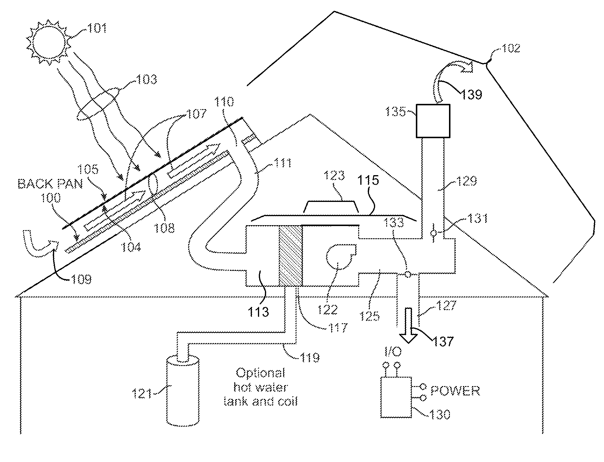
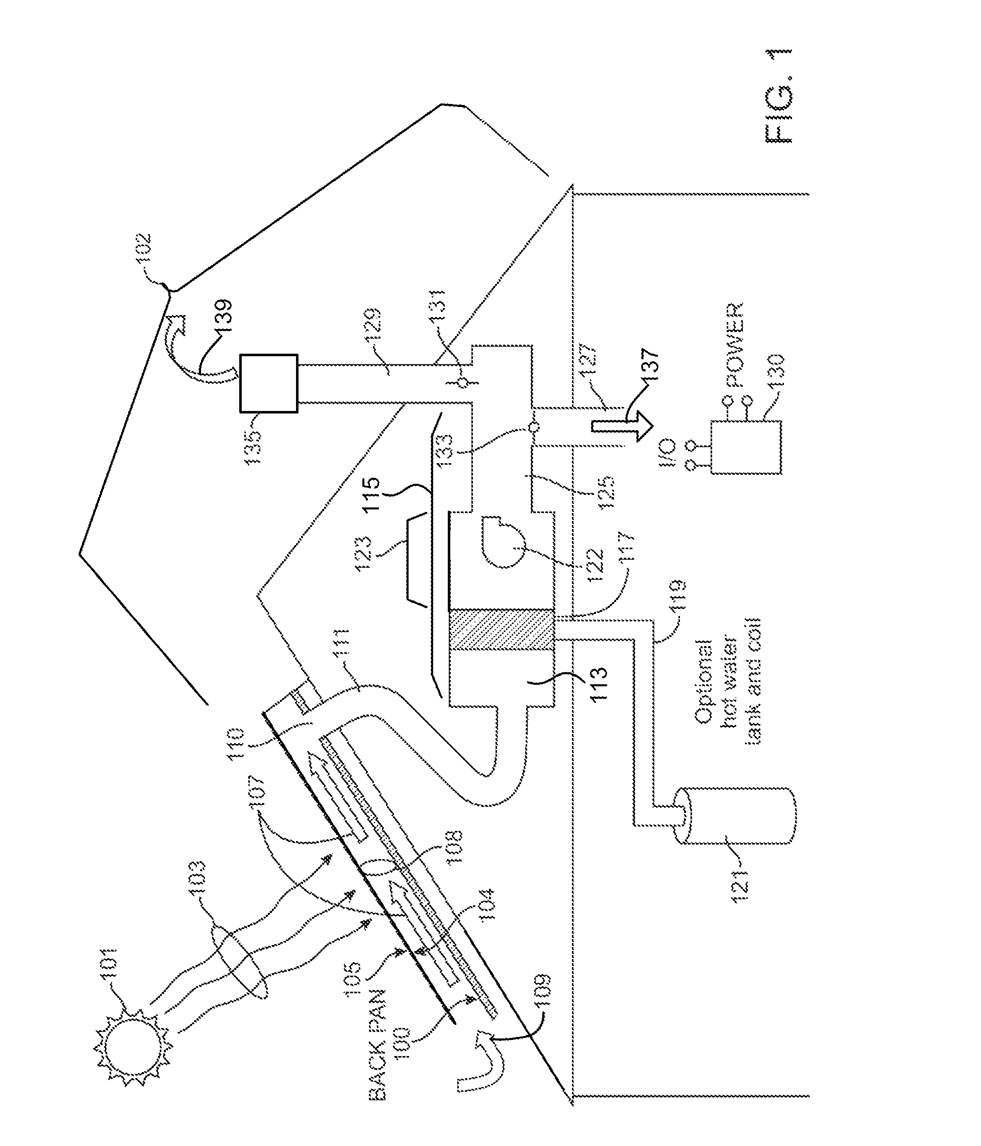
[0033]According to the present invention, techniques related to operation of a thermal solar system are provided. More particularly, the present invention provides a method and system for using a back plate structure to form a plenum for a thermal solar system. Merely, by way of example, the present invention has been applied to a thermal solar module configured on a building structure, but it would be recognized that the invention has a much broader range of applications.

[0034]FIG. 1 is a simplified diagram of a back plate structure 100 for a thermal solar system according to an embodiment of the present invention. This diagram is merely an example, which should not unduly limit the scope of the claims herein. One of ordinary skill in the art would recognize other variations, modifications, and alternatives. As shown, the thermal solar system 102 includes a plurality of thermal modules spatially configured as an N by M array, where N is an integer greater than 1, and M is an intege...


PUM


Abstract

A thermal solar system having a fire rating of at least A. In a specific embodiment, the system includes a thermal solar module having an aperture region and a backside region. The system has a shaped thickness of material having a first side and a second side. In a preferred embodiment, the shaped thickness of material is characterized by a fire rating of at least A. The material has a thickness suitable to be free from penetration of moisture according to one or more embodiments. The thickness of material also has a structural characteristic capable of maintaining a shape and coupling to the backside region of the thermal solar module according to one or more embodiments. The system also has an air plenum provided between the thermal solar module and the thickness shaped thickness of material. In a preferred embodiment, the system further has a frame assembly operably coupled to the shaped thickness of material to support the shaped thickness of material and the thermal solar module.

Description

CROSS-REFERENCE TO RELATED APPLICATIONS[0001]This application claims priority from U.S. application Ser. No. 12 / 638,964, filed Dec. 15, 2009, which claims priority from U.S. Provisional Application No. 61 / 141,623, filed Dec. 30, 2008, commonly assigned, and incorporated by reference for all purposes herein.BACKGROUND OF THE INVENTION[0002]The present invention relates to operation of a thermal solar system. More particularly, the present invention provides a method and system for using a back plate structure to form a plenum for a thermal solar system. Merely, by way of example, the present invention has been applied to a thermal solar module configured on a building structure, but it would be recognized that the invention has a much broader range of applications.[0003]Over the past centuries, the world population of human beings has exploded. Along with the population, demand for resources has also grown explosively. Such resources include raw materials such as wood, iron, and copp...

Claims


Application Information

Patent Timeline
Patent Type & Authority Patents(United States)
IPC IPC(8): E04D13/18F24J2/04
CPCH02S20/23F24J2/045Y02E10/47F24S20/67F24S25/35F24S2020/17H02S20/22H02S40/425H02S40/44Y02B10/10Y02B10/20Y02E10/50Y02E10/60Y02E10/44
Inventor BURTT, ERIC R.
Owner SUNEDISON INC
Why Eureka
Try Eureka