Robot control method, robot control device, robot, and robot system

a robot and control device technology, applied in the direction of programmed manipulators, programme control, instruments, etc., can solve the problem that the workpiece cannot be held stably for a long tim

Inactive Publication Date: 2015-08-11
SEIKO EPSON CORP
View PDF12 Cites 3 Cited by
  • Summary
  • Abstract
  • Description
  • Claims
  • Application Information

AI Technical Summary

Benefits of technology

[0006]An advantage of some aspects of the invention is to provide a robot control method, a robot control device, a robot, and a robot system which can determine a holding form in which an object can continue to be stably held even when a predetermined external force is applied to a robot having a suction mechanism due to the above-mentioned collision, inertial force, increase in weight, or pressing against another object.

Problems solved by technology

However, in the above-mentioned control method, the holding state when a workpiece has been held is checked, but when an external force is applied such as when the workpiece collides with something during work, when an inertial force is applied to the workpiece due to acceleration or deceleration, when the weight of the workpiece increases by attaching another component thereto, or when the workpiece is pressed against another component to attach the component thereto, there is a problem in that slipping occurs on the contact surface of the robot hand and the workpiece and thus the workpiece does not continued to be stably held, such that the holding is not continued or the holding position is changed.

Method used


Image

  • Robot control method, robot control device, robot, and robot system
  • Robot control method, robot control device, robot, and robot system
  • Robot control method, robot control device, robot, and robot system

Examples


first embodiment

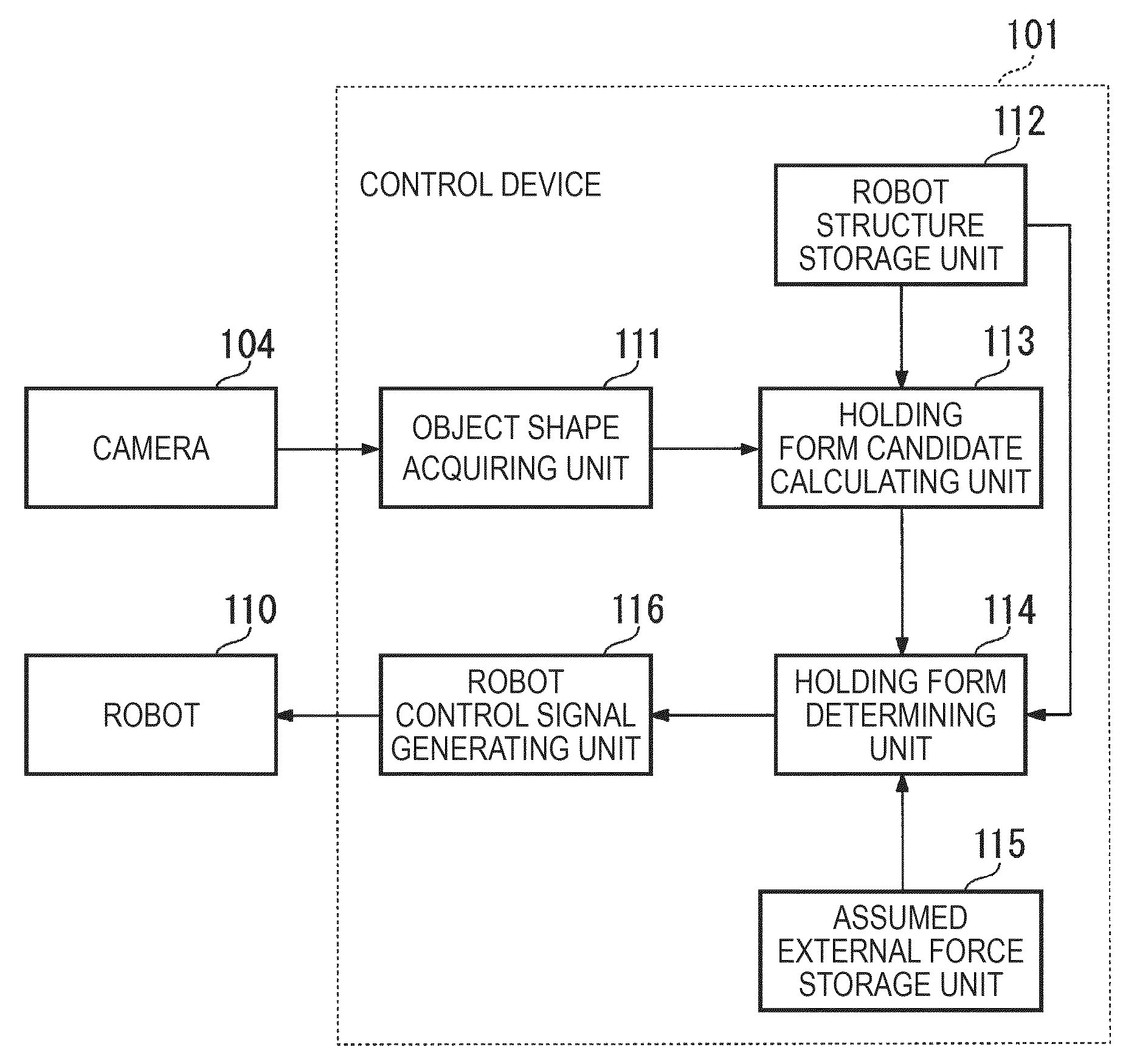
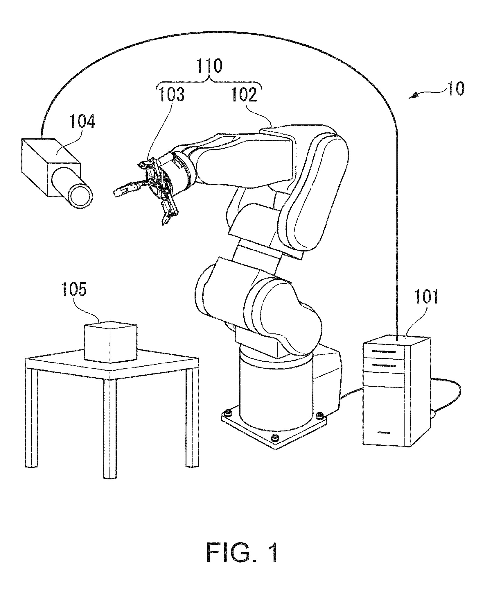
[0037]FIG. 1 is an outside view illustrating a configuration of a robot system 10 according to this embodiment. The robot system 10 according to this embodiment includes a robot 110, a control device 101, and a camera 104. The robot 110 includes a manipulator 102 and a robot hand 103. An object 105 is an example of a workpiece in the robot system. The robot 110 holds the object 105 to perform work.

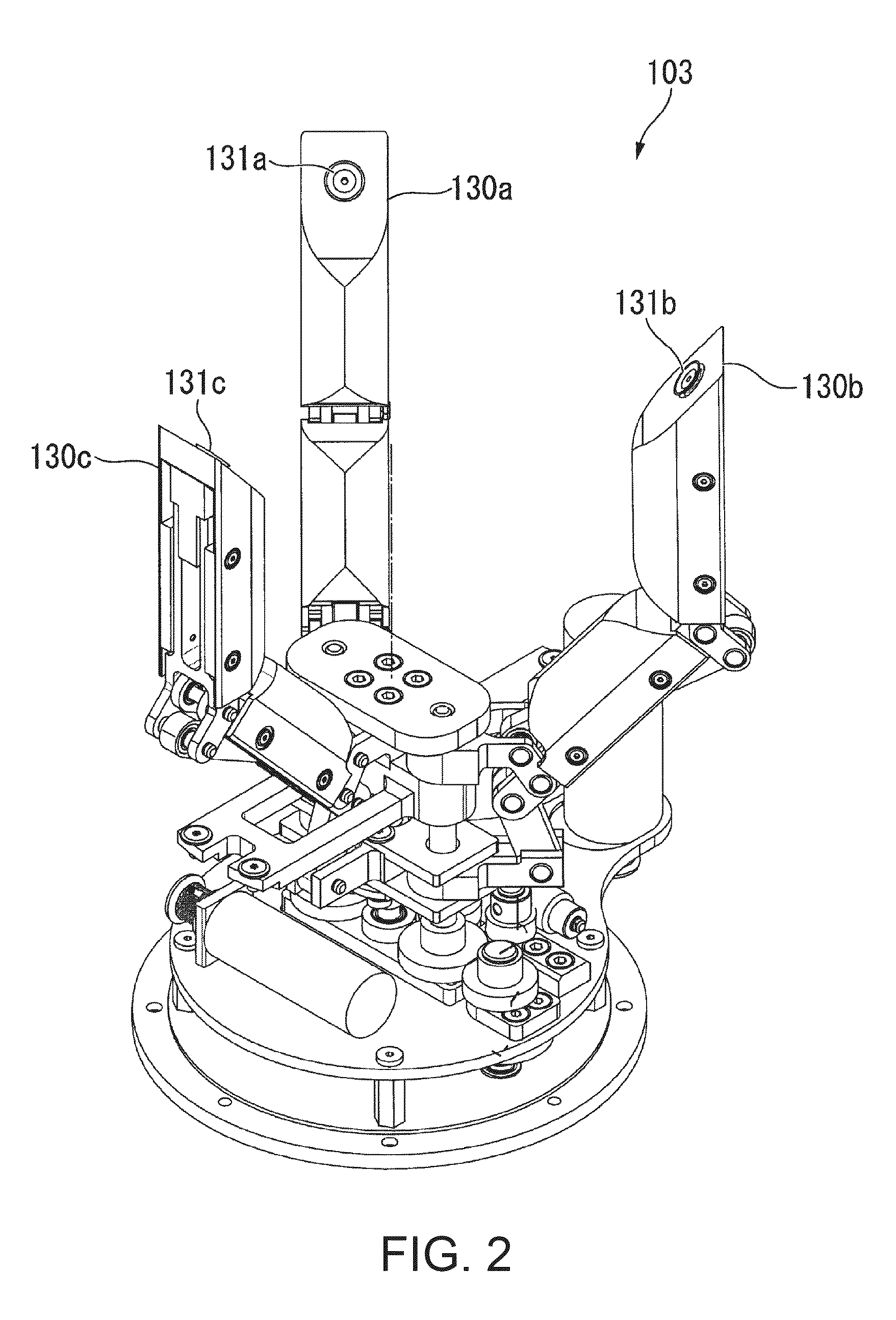
[0038]The robot hand 103 is mounted on a tip of the manipulator 102 and has plural fingers for holding the object 105. One end of the manipulator 102 is fixed to a pedestal or the like and the robot hand 103 is mounted on the other end thereof. The manipulator 102 causes the robot hand 103 to move to a position and a posture for holding the object 105 by causing joints to move. The camera 104 captures an image of the object 105 and inputs an image signal as the imaging result to the control device 101. The camera 104 captures an image of the object 105 from plural viewpoints and inputs the...

second embodiment

[0076]In the first embodiment, the positions at which the fingers 130a, 130b, and 130c of the robot hand 103 come in contact with an object 105 are defined as the holding form. In a second embodiment, the angles formed by the suction mechanisms and the contact surfaces in addition to the positions at which the fingers 130a, 130b, and 130c comes in contact with an object are defined as a holding form. A robot system according to the second embodiment has the same configuration as illustrated in FIG. 1, but is different from the robot system illustrated in FIG. 1 in only parts of the holding form candidate calculating unit 113 and the holding form determining unit 114 of the control device 101. Accordingly, the differences will be described and the other configuration will not be repeated. First, a relationship between the angle formed by the suction mechanism and the contact surface and the suction force will be described below.

[0077]FIG. 12 is a diagram illustrating a variation in c...


PUM


Abstract

A robot control method includes a first step of selecting a holding form in which a robot holds an object and a second step of determining whether the object can continue to be stably held when a predetermined external force is applied to the object in the selected holding form. In the second step, it is determined that the object can continue to be stably held when a force which should be generated by a contact portion to generate resistance to the predetermined external force is included in a friction cone of a force generated by driving the contact portion and enlarged by a suction force from the suction mechanism.

Description

BACKGROUND[0001]1. Technical Field[0002]The present invention relates to a robot control method, a robot control device, a robot, and a robot system.[0003]2. Related Art[0004]In recent years, the following has been known as a method of controlling a suction type robot (see JP-A-2010-69542). A robot hand is first made to move forward to a workpiece holding target position and a holding state is checked. When the holding state is not good, the workpiece holding target position is changed and the robot hand is made to move forward up to the holding state. When the holding state is good, the robot hand is made to move backward so as to take out a workpiece and the holding state is checked again. When the holding state is not good, the workpiece holding target position is changed and the robot hand is made to move again to the changed workpiece holding target position.[0005]However, in the above-mentioned control method, the holding state when a workpiece has been held is checked, but wh...

Claims


Application Information

Patent Timeline
Patent Type & Authority Patents(United States)
IPC IPC(8): B25J9/16B25J15/06
CPCB25J9/1653G05B2219/39542G05B2219/39536G05B2219/39514G05B2219/39505G05B2219/39478B25J15/06B25J9/1612
Inventor NAMMOTO, TAKASHIKOSUGE, KAZUHIROYAMAGUCHI, KENGOHIRATA, YASUHISA
Owner SEIKO EPSON CORP
Why Eureka
Try Eureka