
Intramedullary fixation assembly and method of use

a technology of fixation assembly and intramedullary, which is applied in the direction of prosthesis, internal osteosynthesis, osteosynthesis devices, etc., can solve the problems of dislocation and fracture, dislocation of bone, and deformation of the foo

Active Publication Date: 2015-04-28
EXTREMITY MEDICAL
View PDF329 Cites 25 Cited by
  • Summary
  • Abstract
  • Description
  • Claims
  • Application Information

AI Technical Summary

Problems solved by technology

This condition causes bony fragmentation, dislocation and fractures that eventually progresses to foot deformity, bony prominences, ulceration and instability of the foot.
Charcot arthropathy can affect any joint in the body but is often seen in the feet affecting the metatarsal, tarsometatarsal and tarsal joints and frequently causes the foot to lose its arch or curvature, thus resulting in “flat footedness” in the mid-foot region.
While these devices allow fixation and promote fusion, they do not deliver restoration of the arch in a Charcot Foot.
Moreover, infections and wound complications are a major concern in aforementioned procedures.
Wound closure is technically demanding for the surgeon, and devices that add surface prominence, such as plates or exposed screws, add to the difficulty by requiring greater tissue tension during incision reapproximation.
This increases the risk of postoperative wound infections and dehiscence that may ultimately result in limb amputation.

Method used


Image

  • Intramedullary fixation assembly and method of use
  • Intramedullary fixation assembly and method of use
  • Intramedullary fixation assembly and method of use

Examples


Embodiment Construction

[0044]The invention may be understood more readily by reference to the following detailed description of preferred embodiment of the invention. However, techniques, systems and operating structures in accordance with the invention may be embodied in a wide variety of forms and modes, some of which may be quite different from those in the disclosed embodiment. Consequently, the specific structural and functional details disclosed herein are merely representative, yet in that regard, they are deemed to afford the best embodiment for purposes of disclosure and to provide a basis for the claims herein, which define the scope of the invention. It must be noted that, as used in the specification and the appended claims, the singular forms “a”, “an”, and “the” include plural referents unless the context clearly indicates otherwise.

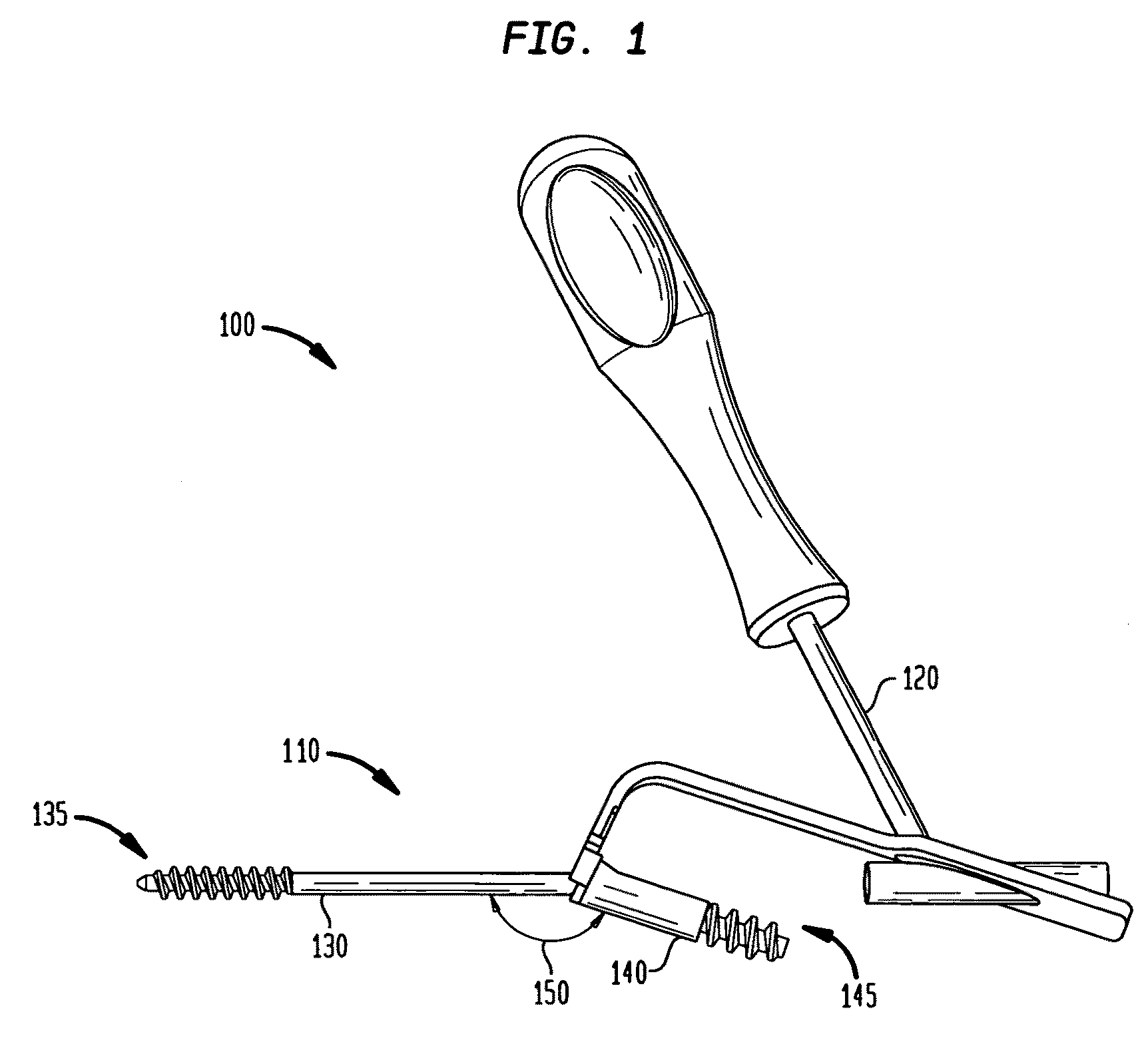
[0045]Referring now to FIG. 1, there is shown a fixation system 100 which is made in accordance with the teachings of the preferred embodiment of the invention. ...


PUM


Abstract

A method for applying compression to a joint includes providing an intramedullary fixation assembly having a proximal screw member positioned at a proximal end of the intramedullary fixation assembly and a lag screw member positioned at a distal end of the intramedullary fixation assembly. Medullary canals are drilled in a first and second bone and the medullary canals are reamed. The proximal screw member is inserted into the first bone and a drill is used create a dorsal hole in the first bone. The lag screw member is slideably coupled to the dorsal hole and to the proximal screw member and into the second medullary canal. A torque is applied to the lag screw member to apply compression to the joint.

Description

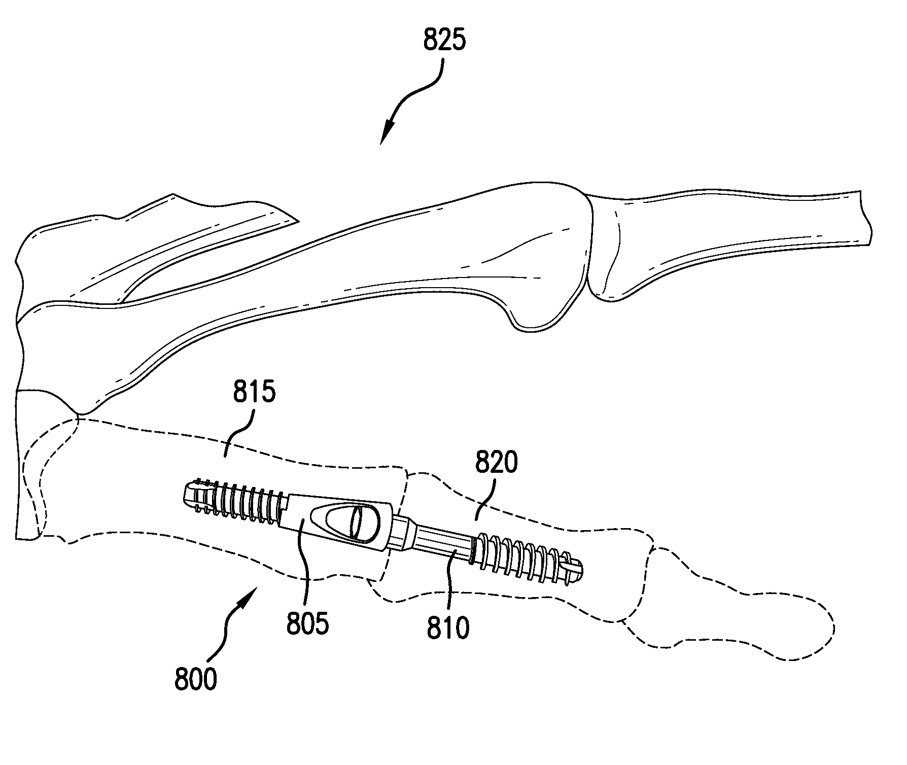
CROSS-REFERENCE TO RELATED APPLICATIONS[0001]This continuation in part application claims the benefit of copending U.S. patent application Ser. No. 12 / 456,808, filed Jun. 23, 2009, which claims the benefit of Provisional Application No. 61 / 132,932, filed Jun. 24, 2008, the entire contents of the entire chain of applications is herein incorporated by reference.FIELD OF THE INVENTION[0002]This invention relates to the field of orthopedic implant devices, and more particularly, to an intramedullary fixation assembly used for internal fixation of angled joints, bones and deformity correction, such as the metacarpal phalangeal joint in the hand.BACKGROUND OF THE INVENTION[0003]Orthopedic implant devices, such as intramedullary nails, plates, rods and screws are often used to repair or reconstruct bones and joints affected by trauma, degeneration, deformity and disease, such as Charcot arthropathy caused by diabetes in some patients. As an example, charcot arthropathy (or Charcot Foot) is...

Claims


Application Information

Patent Timeline
Patent Type & Authority Patents(United States)
IPC IPC(8): A61B17/56A61B17/17A61B17/72A61B17/86A61F2/30A61F2/42
CPCA61B17/7291A61B17/7233A61B17/1717A61B17/72A61B17/8605A61B17/8625A61F2/4241A61F2002/30622A61F2002/3085A61F2002/4238A61F2002/4248A61B2017/1775A61B2017/1782A61B17/1775A61B17/1782A61F2002/4243A61B17/8615A61B17/8685
Inventor TYBER, JEFFGANNOE, JAMYKIEFER, LAWRENCEDONLEY, BRIAN GERARDADAMS, BRIAN
Owner EXTREMITY MEDICAL
Learn More