
Toy projectile launcher apparatus

a projectile launcher and toy technology, applied in the field of toys with projectile launchers, can solve the problems of not revealing or illustrating a superior marketable toy item, too expensive, complicated or insufficiently robust, and difficult to use devices for children, etc., to achieve the effect of convenient operation, easy operation and fun to us

Active Publication Date: 2015-03-03
HASBRO INC
View PDF44 Cites 24 Cited by
  • Summary
  • Abstract
  • Description
  • Claims
  • Application Information

AI Technical Summary

Benefits of technology

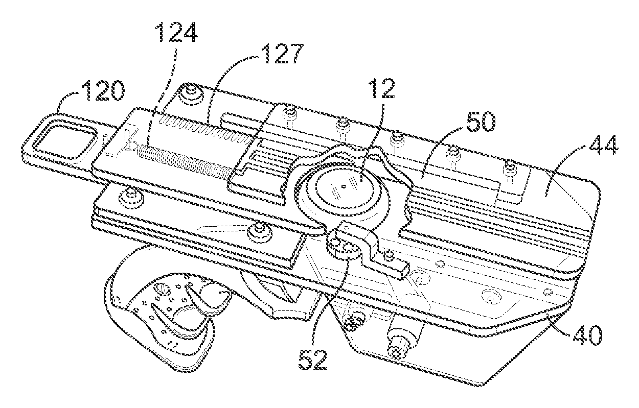
[0008]In accordance with the present invention, an advantageous method and apparatus are provided in the form of a toy projectile launcher apparatus that discharges a soft foam circular projectile. The toy launcher is easily operated, even by young children, and requires a slide to be moved rearward to cock a launch spring, a projectile to be inserted and a lever to be pivoted. Pivoting the lever causes the slide and a projectile receptacle to snap forward in response to another spring such that the projectile is properly located to be contacted by a rotating launch arm once a trigger is pulled. The launcher apparatus also has the advantages of being relatively simple, easy to operate, fun to use, safe, relatively inexpensive, compact and yet, structurally robust.

Problems solved by technology

These devices are often difficult to use or dangerous for children, or are too expensive, complicated or insufficiently robust.
These patents and devices are of some interest, however, they do not disclose or illustrate a superior marketable toy item.

Method used


Image

  • Toy projectile launcher apparatus
  • Toy projectile launcher apparatus
  • Toy projectile launcher apparatus

Examples


Embodiment Construction

[0026]The following description is provided to enable those skilled in the art to make and use the described embodiments set forth in the best mode contemplated for carrying out the invention. Various modifications, equivalents, variations, and alternatives, however, will remain readily apparent to those skilled in the art. Any and all such modifications, variations, equivalents, and alternatives are intended to fall within the spirit and scope of the present invention.

[0027]Referring now to FIGS. 1-5, there is shown an embodiment of the invention in the form of a toy projectile launcher apparatus 10 for discharging circular projectiles provided in the form of an aerodynamic flying disc or a toy projectile having a soft exterior and a more robust interior, somewhat similar to discs commonly referred to as Frisbees, one such projectile 12 being shown in FIGS. 6, 7 and 9-12. The toy projectile is structured to be discharged from a toy launcher apparatus with discharge energy imparted ...


PUM

PropertyMeasurementUnit
lengthaaaaaaaaaa
distanceaaaaaaaaaa
diameteraaaaaaaaaa

Abstract

A toy launcher apparatus for discharging circular projectiles, the apparatus having a housing, lower and upper panels mounted to the housing, supports mounted to the housing, a cocking slide and a slide spring connected to the supports, a projectile receptacle connected to the cocking slide, release levers mounted to the housing, a guide wall mounted to the lower panel, a positioning wheel also mounted to the lower panel, and a trigger mounted to the housing. The lower panel includes a slot positioned parallel to the guide wall but off center relative to a center point of a load projectile. Beneath the lower panel is a rotatable launch arm connected to a torsion spring and a catch structure. The upper and lower panels are parallel to one another and spaced to receive a projectile. The projectile is loaded into the projectile receptacle when the receptacle is exposed during the time the launch arm and torsion spring are cocked by a user pulling rearward on the cocking slide. The launch arm is captured by the catch structure, and the cocking slide and the receptacle are also captured. After loading the projectile, the one of the release levers is activated to snap the cocking slide, the carriage and the loaded projectile to a predetermined launch position. When a user pulls the trigger the launch arm is rapidly rotated by the torsion spring through the slot where the launch arm impacts the loaded and correctly positioned projectile and causes the projectile to be discharge with a spin.

Description

FIELD OF THE INVENTION[0001]The present invention relates generally to a toy projectile launcher apparatus, and, more particularly, to a toy projectile launcher apparatus that discharges a covered circular disc or toy projectile having a soft exterior and somewhat robust interior with good flight characteristics and distance.BACKGROUND OF THE INVENTION[0002]Toys and other devices that discharge disc-like objects have been designed in the past with various housing and internal elements. These devices are often difficult to use or dangerous for children, or are too expensive, complicated or insufficiently robust.[0003]Launching devices, toy and otherwise, are well known and are disclosed in several existing patents. By way of example, Napier patented a launching device in 1920 and 1921, U.S. Pat. No. 1,353,663 for a “Target Throwing Device” and U.S. Pat. No. 1,374,757 for a “Catapult.” These patents purport to disclose a launching device for clay pigeon targets and include a slanted p...

Claims


Application Information

Patent Timeline
Patent Type & Authority Patents(United States)
IPC IPC(8): F41B7/08
CPCF41A19/52F41B3/03F41B7/003F41B7/08Y10T29/49863
Inventor VICTOR, ROBERT JAMESJABLONSKI, BRIAN
Owner HASBRO INC
Learn More