
Handheld pneumatic grinder with adjustable wheel guard structure

a pneumatic grinder and adjustable technology, applied in the field of hand-held grinders, can solve the problems of large and complicated structure, difficult to be used in a small spaced working site, and large structur

Inactive Publication Date: 2015-01-27
SUNMATCH INDAL
View PDF16 Cites 6 Cited by
  • Summary
  • Abstract
  • Description
  • Claims
  • Application Information

AI Technical Summary

Benefits of technology

[0007]The primary object of the present invention is to provide a handheld pneumatic grinder, whereby the angle position of the protective hood can be adjusted without using an external tool, and the grinder can be applied in a working site having small space.
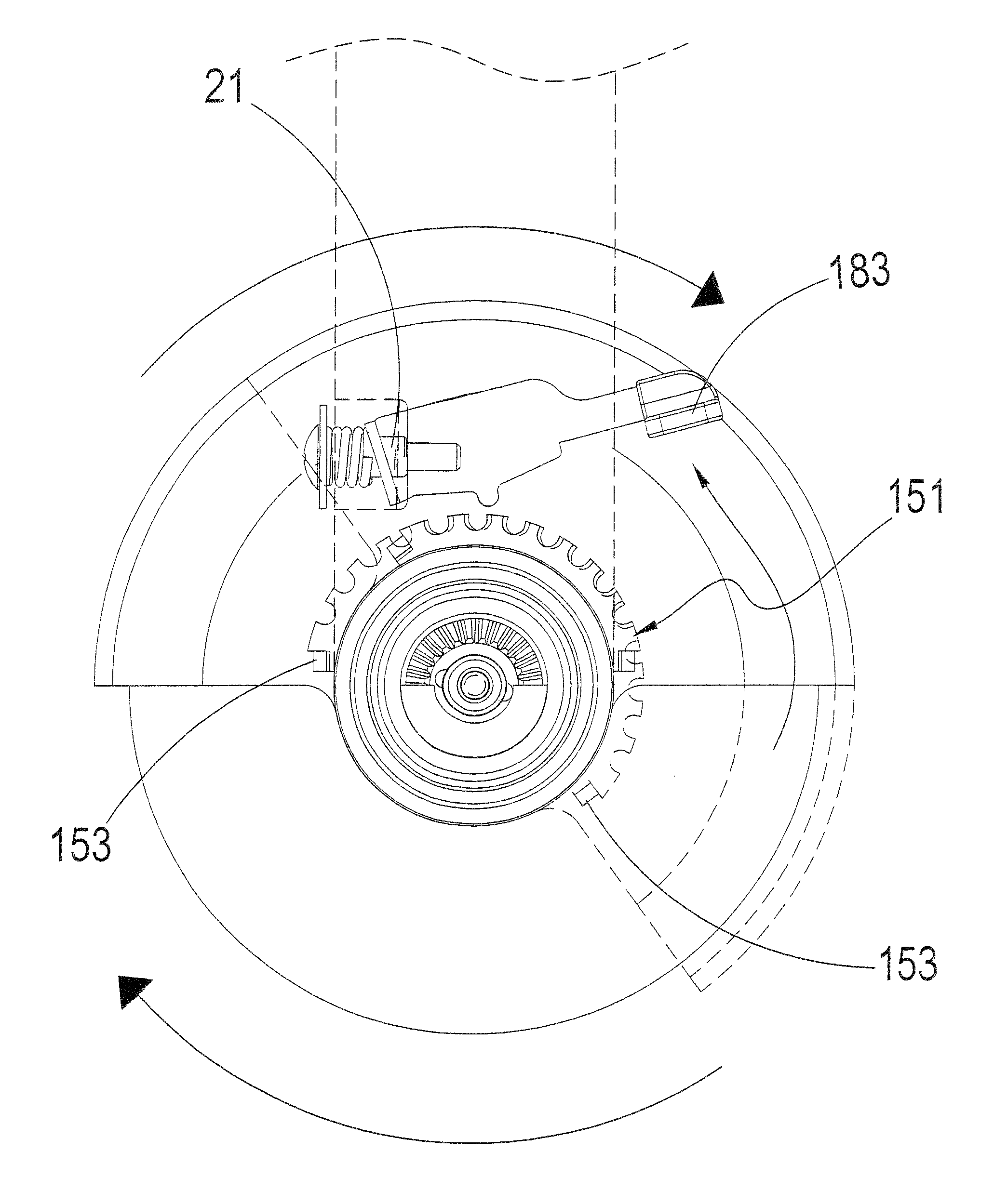
[0009]In operation, the user can is required to depress the operation portion of the control member by one hand. Meanwhile, the protective hood can be rotated by the other hand. After the protective hood is rotated to a desired angle position, the user may release the operation portion of the control member to allow the control member to be engaged with the engagement means of the protective hood again, so that the protective hood can be fixed again. The present invention allows the protective hood to be adjusted without using an external tool, and can achieve a compact design.

Problems solved by technology

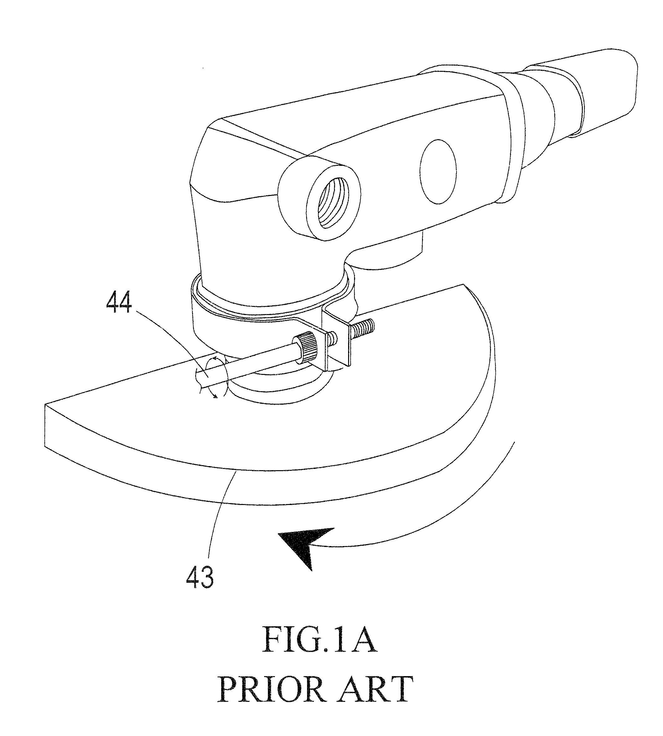
However, to adjust the protective hood 43, an external tool 44 is required to loosen the clamp, so that the protective hood 43 can be rotated to a desired angle, and this is inconvenient.
As to other types of grinders, although they are provided with an adjustable hood, they are large and complicated in structure.
For application in a narrow space, they are inconvenient.
Although U.S. Pat. Nos. 4,924,635 and 7,892,075 disclosed a protective hood that can be adjusted without using an external tool, they are large in structure and thus are difficult to be used in a working site having small space.

Method used


Image

  • Handheld pneumatic grinder with adjustable wheel guard structure
  • Handheld pneumatic grinder with adjustable wheel guard structure
  • Handheld pneumatic grinder with adjustable wheel guard structure

Examples


Embodiment Construction

[0021]Referring to FIGS. 2-5, a handheld pneumatic grinder according to one embodiment of the present invention generally comprises a main body 1, a transmission portion 12, and a wheel guard structure including a coupling member 3, a protective hood 15, and a control member 18.

[0022]The main body 1 defines an active space 10 and is provided with a button 100 for starting the grinder. The transmission portion 12 is provided on the main body 1. The coupling member 13 is coupled to the main body 1 around the transmission portion 12. Also, the main body 1 defines a slot 11, near to the transmission portion 12, for cooperating with the protective hood 15, so that rotation of the protective hood 15 can be limited in a range, as will be fully illustrated later.

[0023]A snap ring 14 is further provided for holding the protective hood 15 onto the coupling member 13 that is coupled to the main body 1. Also, the present invention provides at least one first washer 16 between the snap ring 14 a...


PUM


Abstract

A handheld pneumatic grinder comprises a main body, a transmission portion, and a wheel guard structure. The main body defines an active space. The transmission portion is provided on the main body. The wheel guard structure includes a coupling member, a protective hood, and a control member. The coupling member is coupled to the main body around the transmission portion. The protective hood is rotatably mounted to the coupling member at a center thereof, wherein the protective hood is provided with an engagement means defining a plurality of indentations. The control member has a protrusion, which can engage with one of the indentations of the engagement means to allow the protective hood to be fixed in an angle position. The present invention allows the protective hood to be adjusted without using an external tool, and can achieve a compact design.

Description

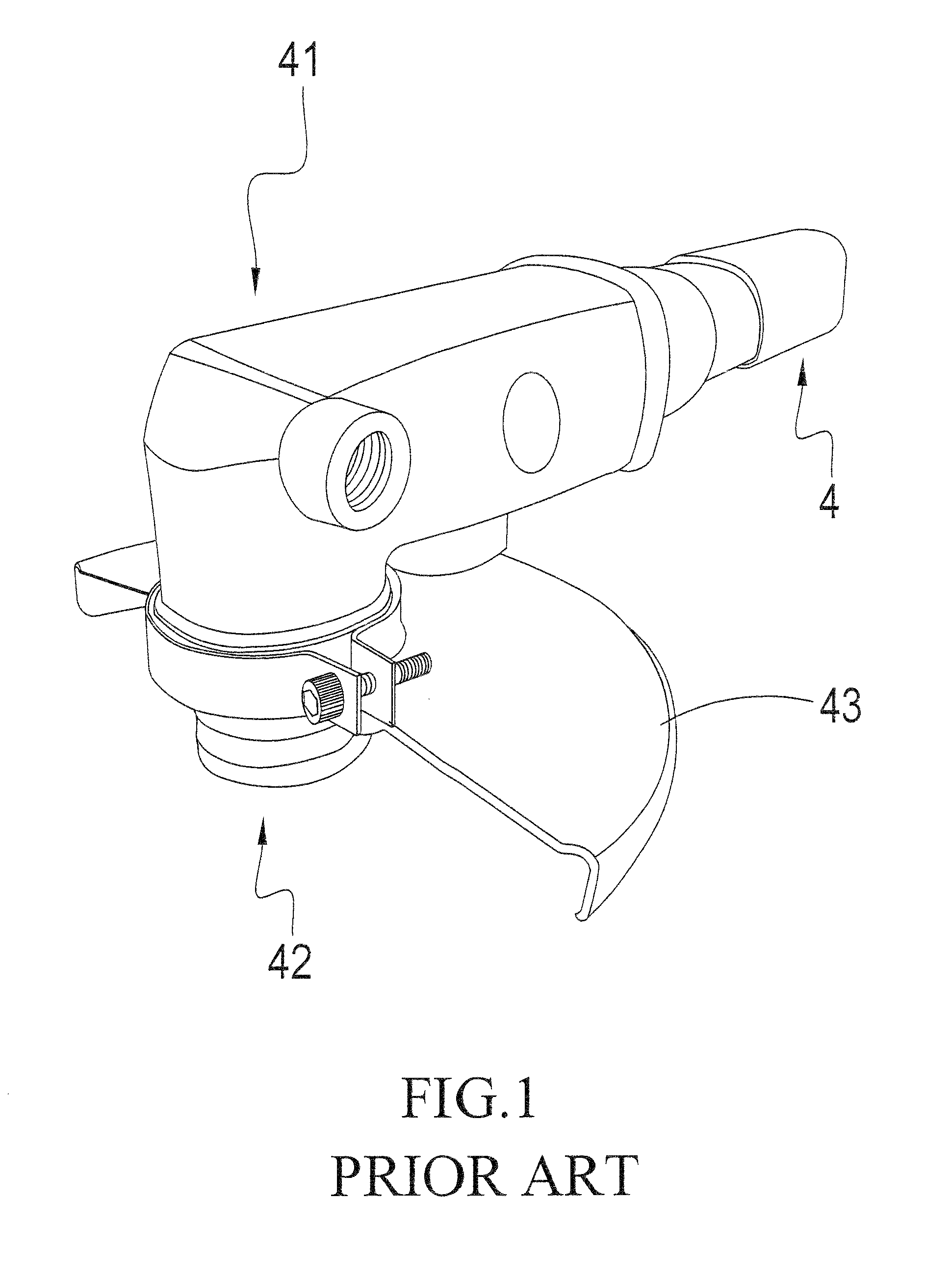
TECHNICAL FIELD OF THE INVENTION[0001]The present invention relates to a handheld grinder and, more particularly, to a handheld pneumatic grinder, whereby the angle position of the protective hood can be adjusted without using an external tool, and the grinder can be applied in a working site having small space.DESCRIPTION OF THE PRIOR ART[0002]As shown in FIGS. 1 and 1A, a conventional handheld grinder comprises a main body 41, a handle 4, and a transmission portion 42, which is driven through a direction converter consisting of bevel gears within the transmission portion 42. For safety, a protective hood 43 is usually provided and mounted around the transmission portion 42.[0003]In use, a grinding wheel (not shown) is mounted to the transmission portion 42, and then can be driven into rotation through an input axle in the handle 4. For protecting a user from being damaged due to breakage of the grinding wheel, the protection hood 43 is mounted around the transmission portion 42 by...

Claims


Application Information

Patent Timeline
Patent Type & Authority Patents(United States)
IPC IPC(8): B24B55/05
CPCB24B23/028B24B55/052
Inventor CHEN, LUNG-PAO
Owner SUNMATCH INDAL
Learn More