
Personal floatation device

a floatation device and personal technology, applied in the field of floatation devices, can solve the problems of difficult deployment, difficult use, stigma for wearers,

Inactive Publication Date: 2014-12-30
MCCARTHY DANIEL P
View PDF12 Cites 9 Cited by
  • Summary
  • Abstract
  • Description
  • Claims
  • Application Information

AI Technical Summary

Benefits of technology

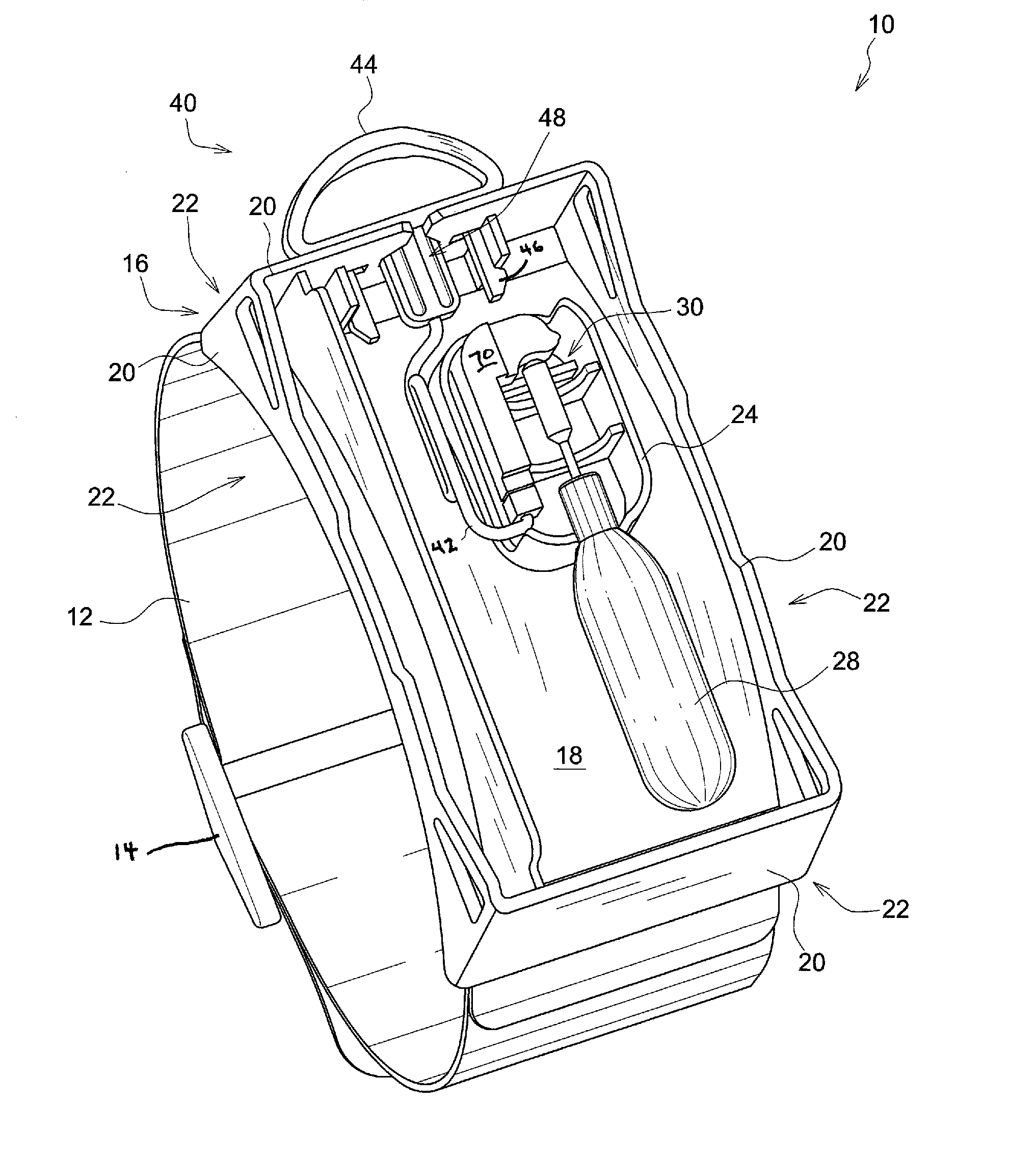
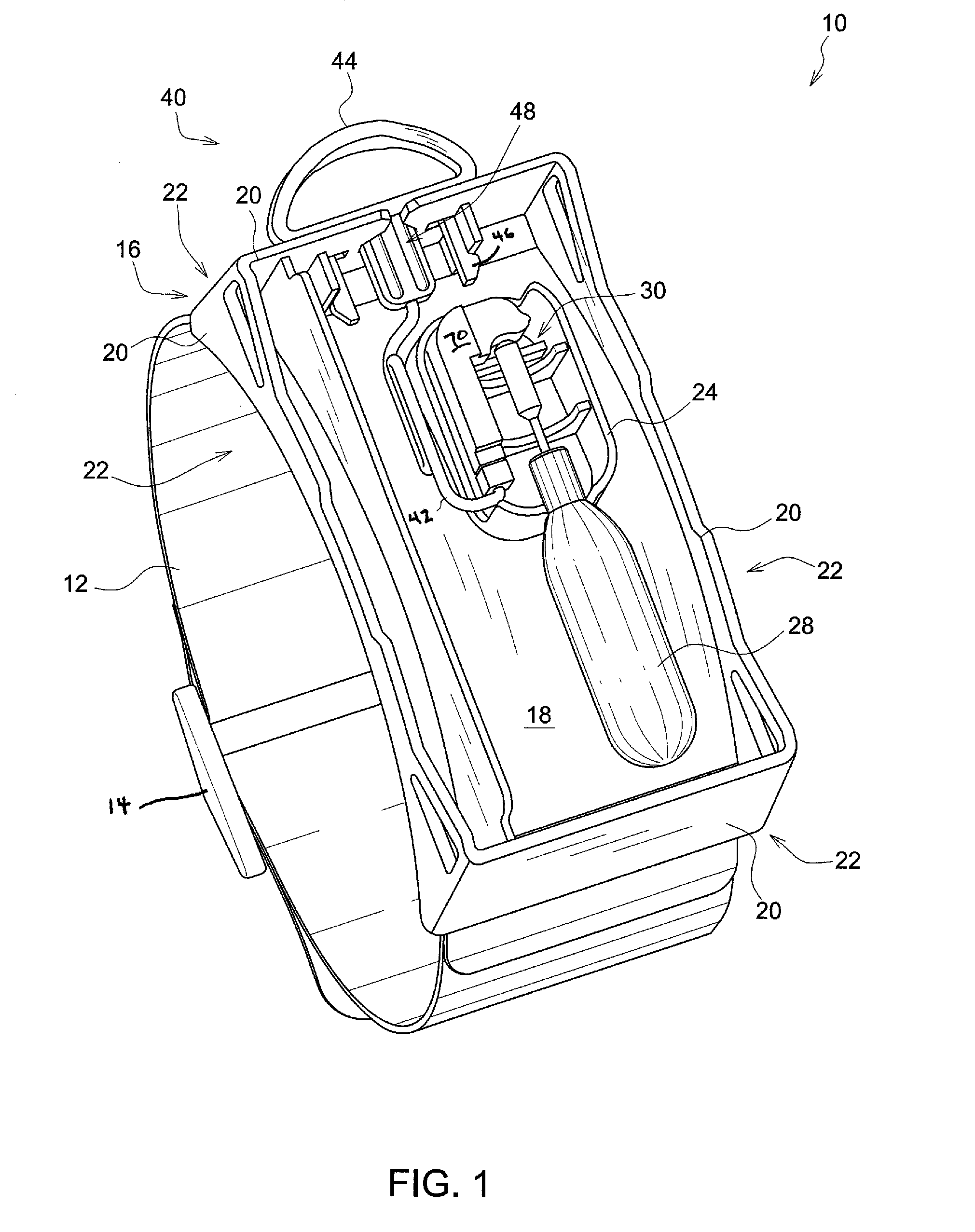
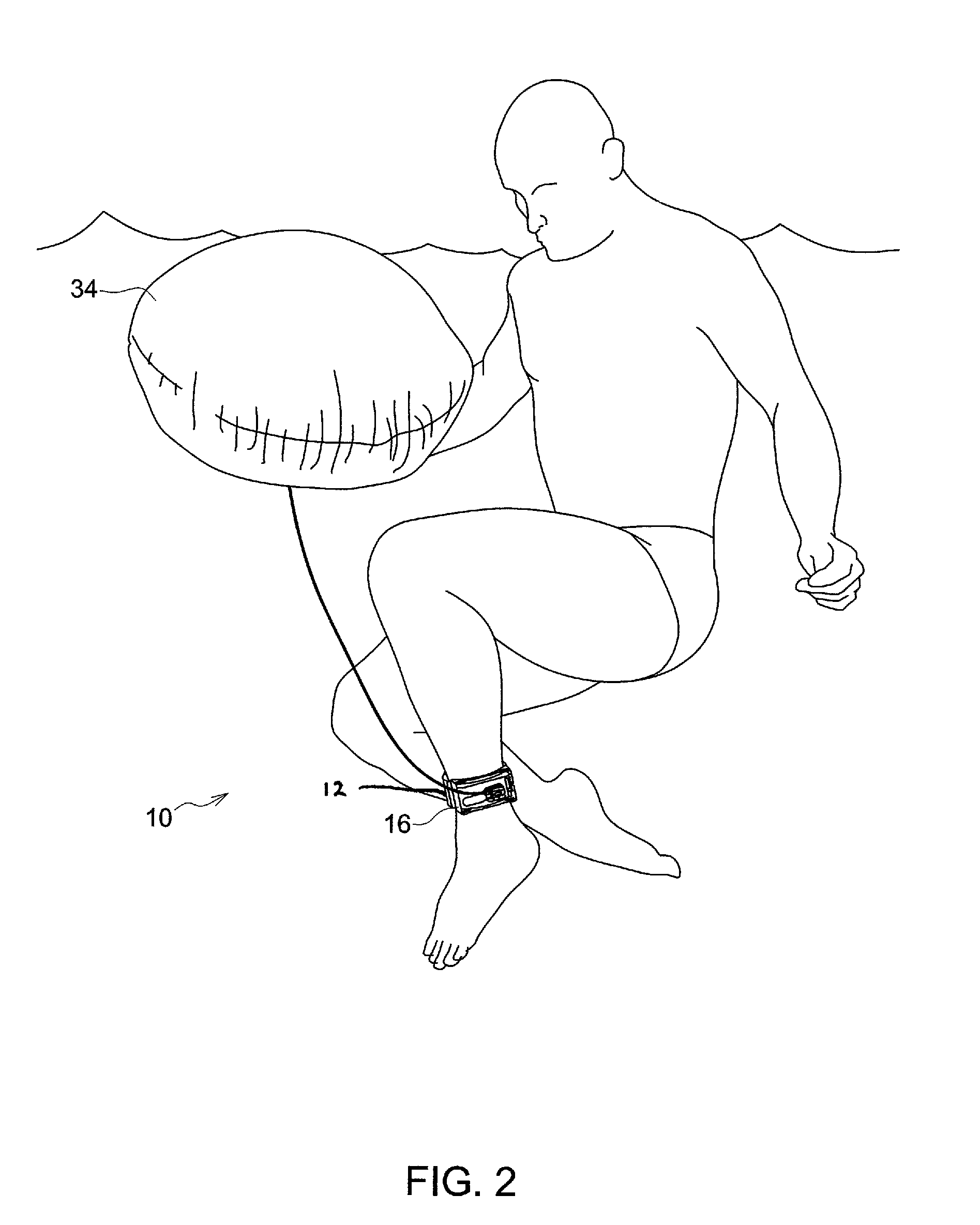
The present invention is a personal floatation device that solves problems in the art. It includes an attachment device that selectively attaches to a user's body, an adjustment device that selectively adjusts the attachment device to the user's body, and a housing that selectively removably attaches to the attachment device. The housing includes a compressed air container and a compressed air activation device that, when triggered, releases air. The housing also includes an air bladder that inflates upon release of air. The housing has a breakaway cover that detaches when exposed to pressure from the air bladder inflating. The invention also includes a trigger device that selectively activates the compressed air activation device. The trigger device has a breakaway grasping structure that breaks away from the housing when significant force is applied. The breakaway grasping structure includes barbs that release the trigger device from the housing. The invention also includes a slot through the outer wall of the housing through which the trigger device is disposed. The technical effects of the invention include improved safety and comfort for users in water activities.

Problems solved by technology

The inventions heretofore known suffer from a number of disadvantages which include but not limited to not being adapted to use by children, being difficult to use, being difficult to deploy, imputing a stigma to the wearer, requiring complicated actions, restricting motion of the user, being heavy, being cumbersome, failing to provide peace of mind, being subject to accidental deployment, being vulnerable to environmentally induced damage, being expensive to manufacture, being difficult to wear, substantially interfering with actions and / or motions required in water sports, and being bulky.

Method used


Image

  • Personal floatation device
  • Personal floatation device
  • Personal floatation device

Examples


Embodiment Construction

[0030]For the purposes of promoting an understanding of the principles of the invention, reference will now be made to the exemplary embodiments illustrated in the drawing(s), and specific language will be used to describe the same. It will nevertheless be understood that no limitation of the scope of the invention is thereby intended. Any alterations and further modifications of the inventive features illustrated herein, and any additional applications of the principles of the invention as illustrated herein, which would occur to one skilled in the relevant art and having possession of this disclosure, are to be considered within the scope of the invention.

[0031]Reference throughout this specification to an “embodiment,” an “example” or similar language means that a particular feature, structure, characteristic, or combinations thereof described in connection with the embodiment is included in at least one embodiment of the present invention. Thus, appearances of the phrases an “em...


PUM


Abstract

A personal floatation device includes an attachment device that selectably couples to a user's body. The personal floatation device includes a housing that couples to the attachment device. The housing includes a base and an outer wall extending outwardly from a perimeter of the base. The housing includes an inner wall enclosed by the outer wall and extending outwardly from an interior region of the base. The housing includes a compressed air container extending through the inner wall. The housing includes a compressed air activation device functionally coupled to the compressed air container such that, when triggered, releases air therefrom. The housing includes an air bladder in fluid communication with the compressed air container. The housing includes a breakaway cover coupled to the outer wall that detaches when exposed to pressure from the air bladder inflating. The housing include a trigger device functionally coupled to the compressed air activation device.

Description

CROSS-REFERENCE TO RELATED APPLICATIONS[0001]This invention claims priority, under 35 U.S.C. §120, to the U.S. Provisional Patent Application No. 61 / 691,095 by Daniel P. McCarthy filed on Aug. 20, 2013, which is incorporated by reference herein in its entirety.FIELD OF THE INVENTION[0002]The present invention relates to floatation devices, specifically to a personal floatation devices.DESCRIPTION OF THE RELATED ART[0003]A personal flotation device (abbreviated as PFD; also referred to as, lifejacket, life preserver, Mae West, life vest, life saver, cork jacket, buoyancy aid, flotation suit, etc.) is a device designed to assist a wearer, either conscious or unconscious, to keep afloat.[0004]Devices designed and approved by authorities for use by civilians (recreational boaters, sailors, canoeists, kayakers, etc.) differ from those designed for use by passengers and crew of aircraft (helicopters, airplanes) and of commercial vessels (tugs, passenger ferries, cargo ships). Devices used...

Claims


Application Information

Patent Timeline
Patent Type & Authority Patents(United States)
IPC IPC(8): B63C9/19B63C9/00B63C9/13B63C9/08
CPCB63C2009/131B63C9/00B63C9/19B63C9/081
Inventor MCCARTHY, DANIEL, P.
Owner MCCARTHY DANIEL P
Learn More