
Portable ladder with a stand off device

a technology of stand-off device and ladder, which is applied in the direction of ladders, building scaffolds, building aids, etc., can solve the problems of inability to store in a small space (e.g. in a service van) and the size of the known stand-off devi

Active Publication Date: 2014-09-30
LAMPE HLDG
View PDF13 Cites 4 Cited by
  • Summary
  • Abstract
  • Description
  • Claims
  • Application Information

AI Technical Summary

Benefits of technology

[0009]The stand off arm assemblies according to the first aspect of the invention allow for a small or possibly minimal storage space of the ladder.
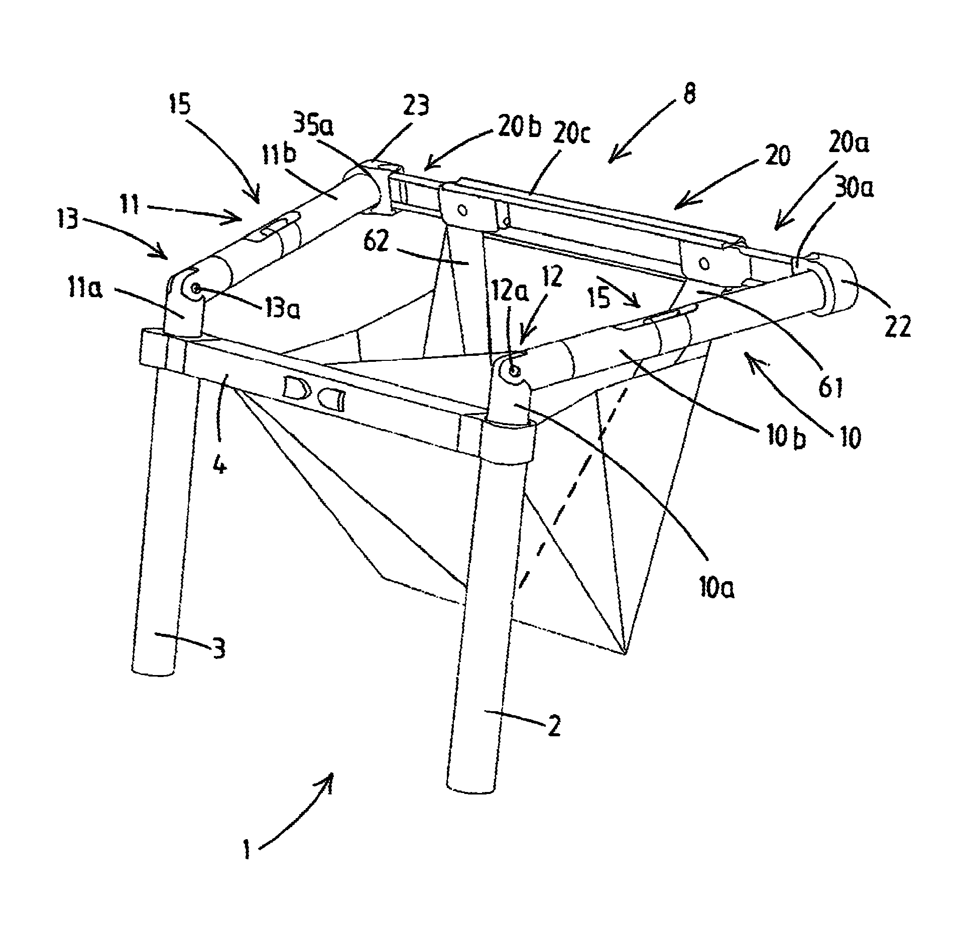
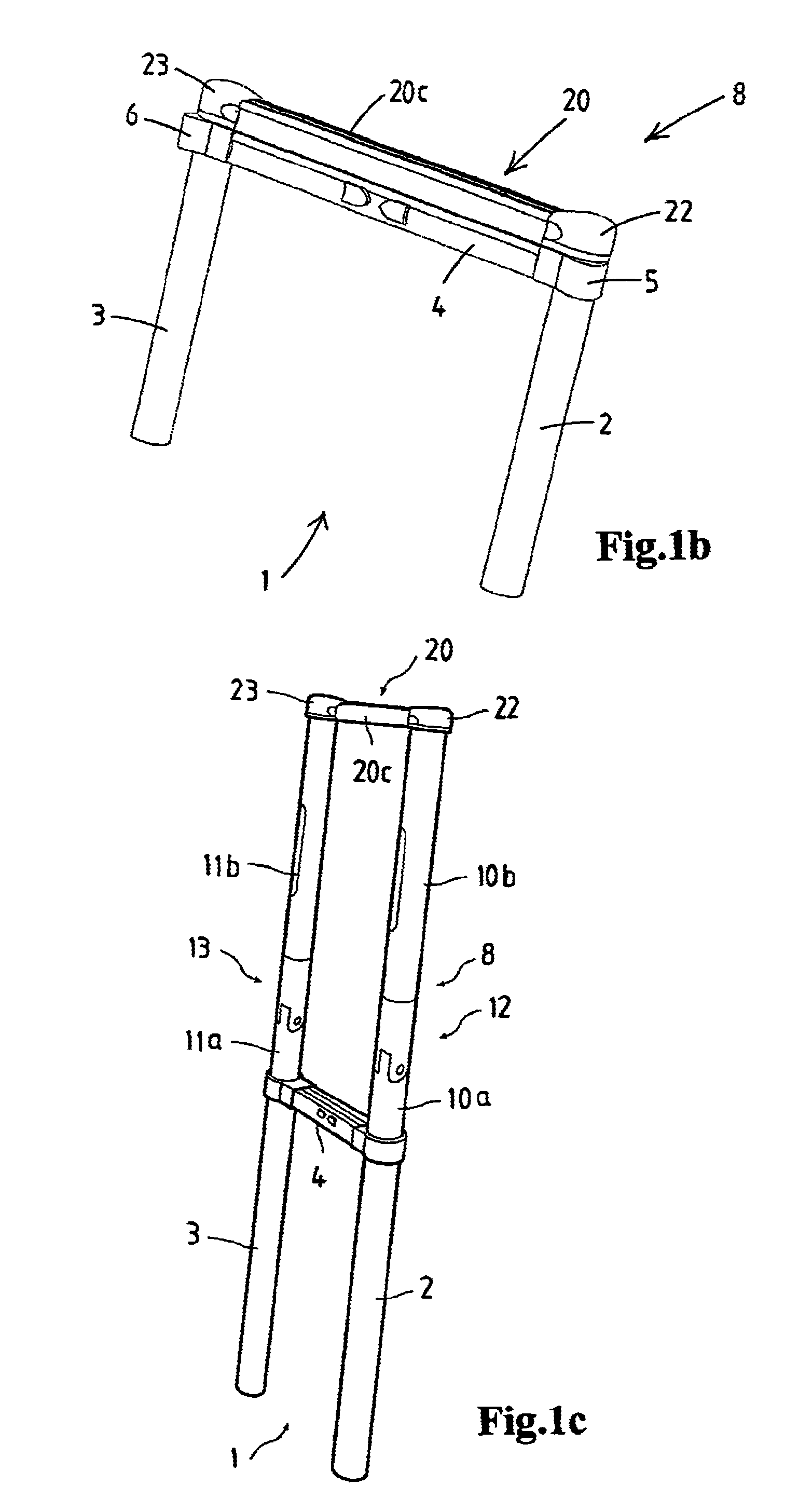
[0086]characterized in that each stand off arm is adapted to be stored in a respective tubular stile of the ladder and to be withdrawn fully from the stile for use of the stand off device, and in that the ladder includes in its upper region, preferably at or near the upper end of each stile, a connector part for each stand off arm, the stand off arm and the connector part having cooperation latching means for latching the stand off arm to the connector part, the ladder allowing the user to withdraw each stand off arm from its stored position in the tubular stile and to latch the stand off arm to the connector part, and in that the connector part is adapted to retain the stand off arm in an angled stand off position with respect to the stile of the ladder.

Problems solved by technology

For instance the size of the known stand off devices is bulky or makes the ladder with the stand off device bulky, e.g. with regard to storage of the ladder.
For example with the ladder in WO2009 / 019162 the user will normally choose to remove the stand off arms when storing the telescopic ladder, as their size and shape makes storage in a small space (e.g. in a service van) impossible.

Method used


Image

  • Portable ladder with a stand off device
  • Portable ladder with a stand off device
  • Portable ladder with a stand off device

Examples


Embodiment Construction

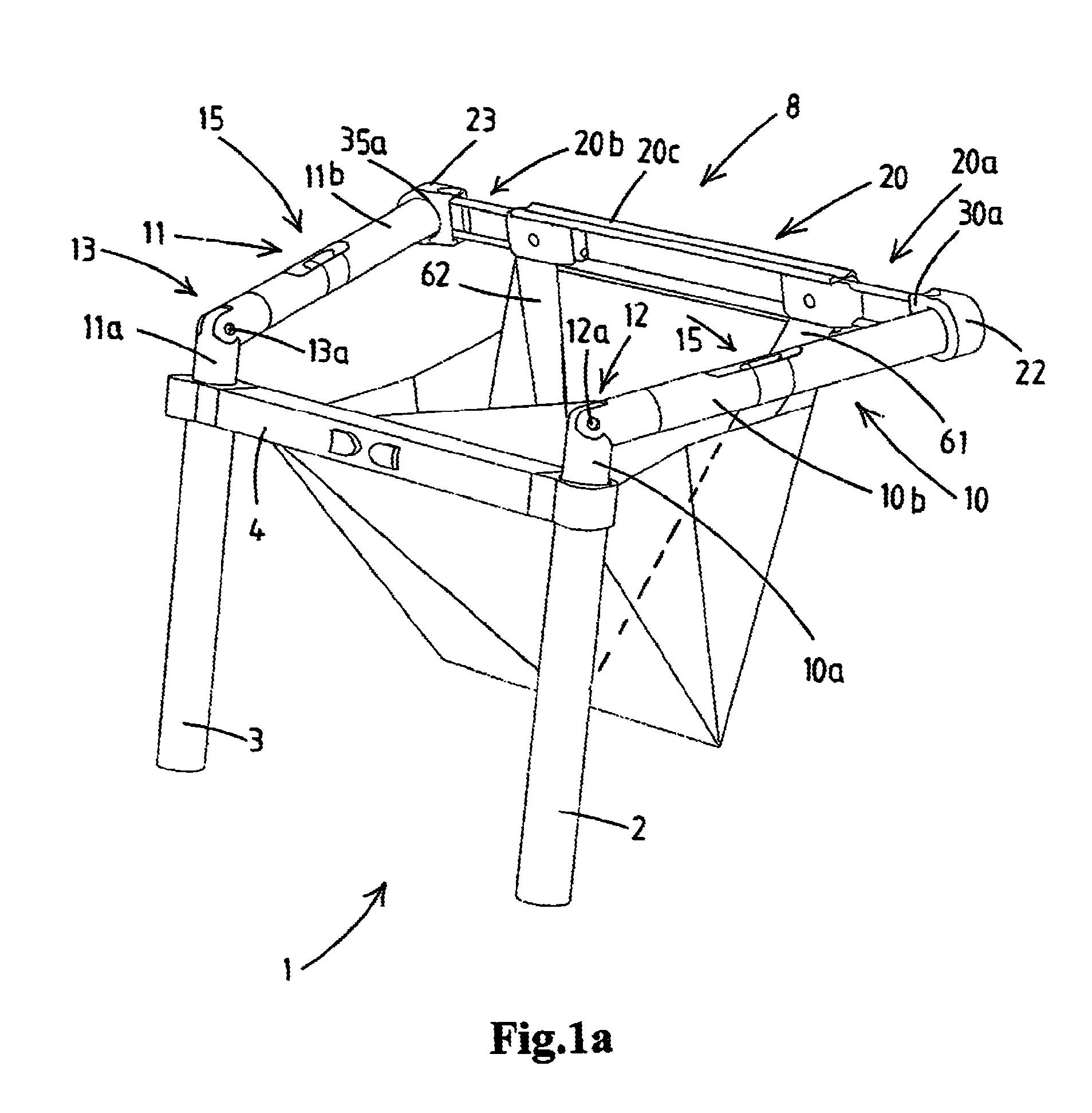
[0111]The FIGS. 1A-7 only show the upper ladder section 1 of a telescopically extendable and collapsible portable ladder. This ladder further has multiple further ladder sections. Each of the ladder sections has two tubular stiles members 2,3 arranged parallel to each other and interconnected by a ladder rung4. The stile members of each ladder section are telescopically inserted into the stile members of an adjacent ladder section. The ladder further comprises latch mechanisms for locking the telescopically inserted stile members relative to one another when the ladder sections are extended. As explained telescopic ladders of such design are known for example from WO2009 / 057995 or WO02 / 101189.

[0112]It will be appreciated that none of the aspects of the invention are limited to such telescopic ladders. Other telescopic designs, or even rigid, non-telescopic ladders may also benefit from one or more aspects of the invention. However, the integration of one or more of the aspects of th...


PUM


Abstract

A portable ladder has two stiles interconnected by rungs. The ladder is provided with a stand off device, including two stand off arm assemblies, each being telescopically inserted into a receiving space. Each stand off arm assembly has a base part and a stand off arm interconnected by a hinge that allows the stand off arm to be pivoted between a position in alignment with the base part and an angled stand off position. The stand off arm assemblies are each configured such that—in extended position—the hinge is located outside the receiving space with the base part being located within said receiving space, and also such that—in retracted position—the base part, the hinge, as well as at least a portion of the stand off arm are located within the receiving space.

Description

CROSS-REFERENCE TO RELATED APPLICATIONS[0001]This application is the National Stage of International Application No. PCT / NL2010 / 050656, filed Oct. 6, 2010, which claims the benefit of Netherlands Application No. 2003605, filed Oct. 7, 2009, the contents of which is incorporated by reference herein.FIELD OF THE INVENTION[0002]The present invention relates to a portable ladder with a stand off device arranged in the upper region of the ladder. In general a stand off device serves to space the upper region of the ladder from the object against which the stand off device is placed. For instance, the object is a wall, a pole, a mast, a structural column, a tree, a corner of a building, etc. In general the use of a stand off device provides for increased safety and comfort for a person standing on the ladder, as the person does not have to be as close to the object as when no stand off device was used.BACKGROUND OF THE INVENTION[0003]It is observed that many designs of stand-off devices a...

Claims


Application Information

Patent Timeline
Patent Type & Authority Patents(United States)
IPC IPC(8): E06C7/48E06C7/14E06C7/18
CPCE06C7/14E06C7/48E06C7/182E06C1/12
Inventor LAMPE, CASPAR BERNARDOLDEN, MAARTEN
Owner LAMPE HLDG
Learn More