
Screen surface forming system

a technology of surface forming and screen, which is applied in the direction of screening, solid separation, chemistry apparatus and processes, etc., can solve the problems of virtually useless screen elements, significantly less efficient, and in any event, the screen system

Inactive Publication Date: 2014-08-12
LUMSDEN CORP
View PDF10 Cites 5 Cited by
  • Summary
  • Abstract
  • Description
  • Claims
  • Application Information

AI Technical Summary

Benefits of technology

[0003]An object of the present invention is to provide a novel and unobvious screen system that includes a plurality of screen elements that can be readily removed and replaced to readily vary one or more characteristics of the screen surface formed by the screen system.
[0004]Another object of a preferred embodiment of the present invention is to provide a screen system that can accommodate screen elements of different structural stability and yet prevent deformation of any of the screen elements including screen elements that typically would be deformed due to the weight of the product being screened.
[0005]A further object of a preferred embodiment of the present invention is to provide a screen system with a support system for supporting one or more screen elements of the screen system where the support system prevents deformation of one or more screen elements that typically would deform due to the weight of the product being screened.

Problems solved by technology

However, this screen system has one or more significant disadvantages.
Deformation of the screen element can render the screen element practically useless and in any event significantly less efficient.

Method used


Image

  • Screen surface forming system
  • Screen surface forming system
  • Screen surface forming system

Examples


Embodiment Construction

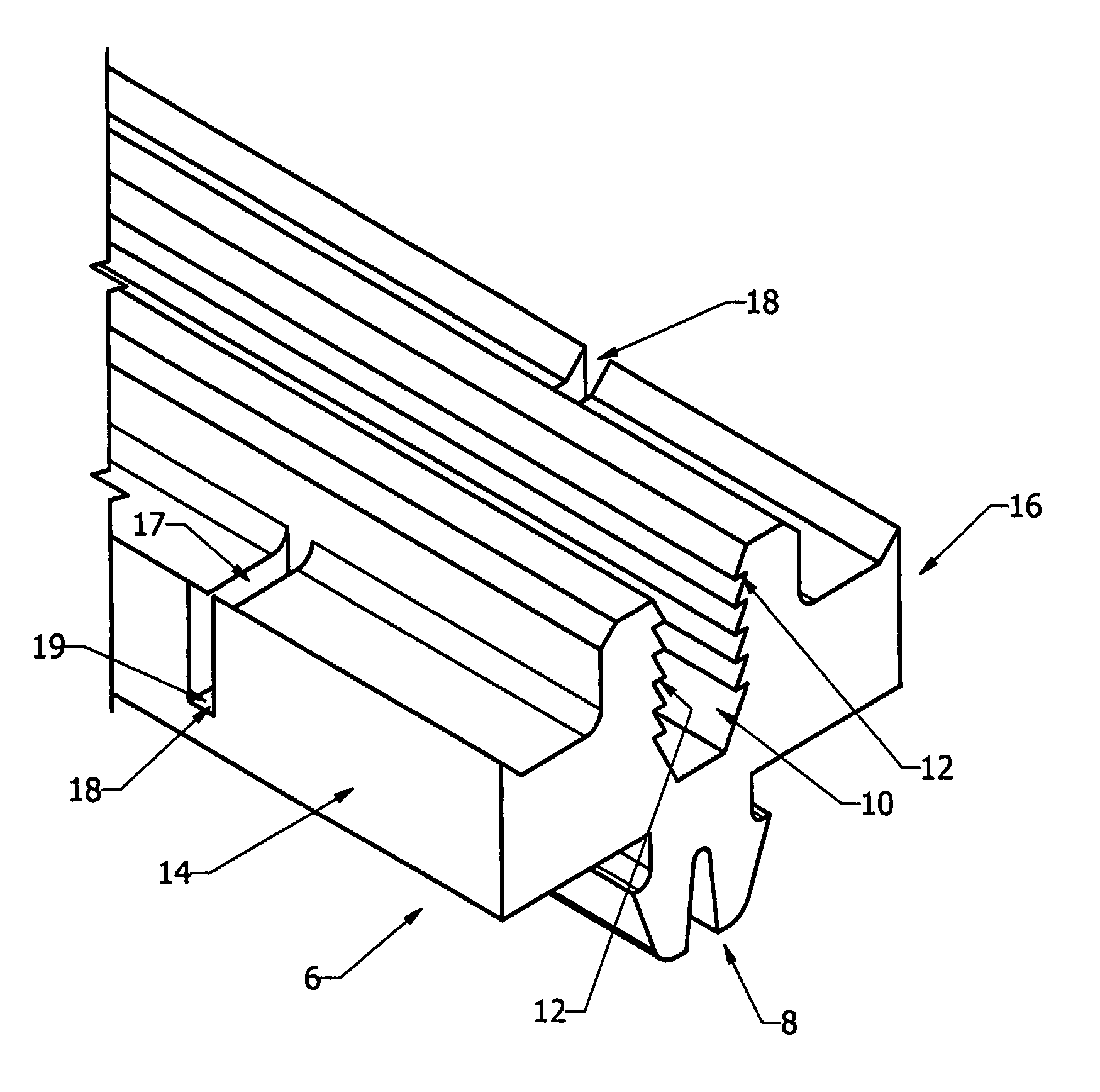
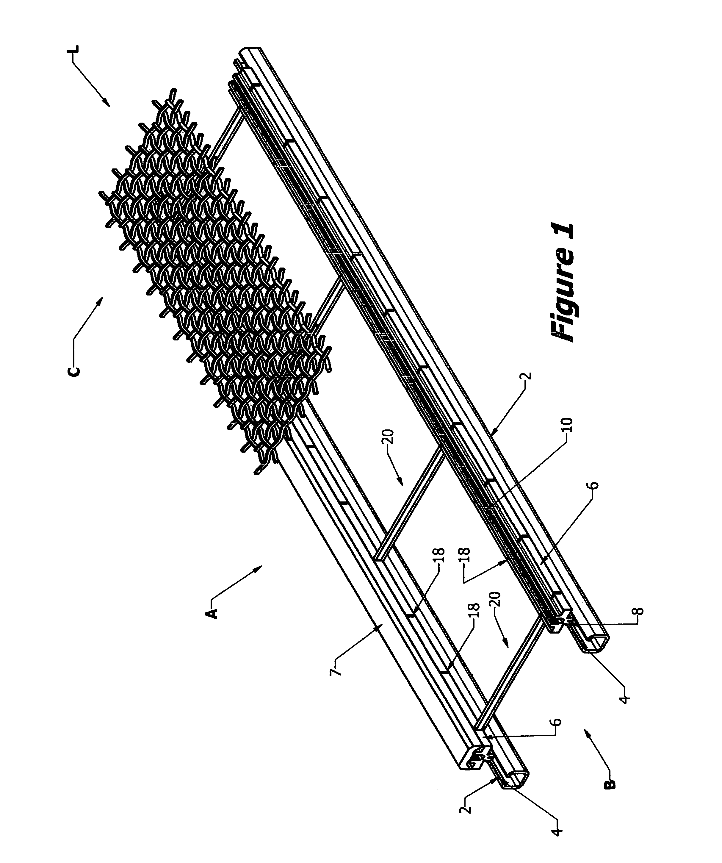
[0027]The preferred forms of the invention will now be described with reference to FIGS. 1-11. The appended claims are not limited to the preferred forms and no term and / or phrase used herein is to be given a meaning other than its ordinary meaning unless it is expressly stated that the term and / or phrase shall have a special meaning.

FIGS. 1-5

[0028]Referring to FIGS. 1 to 5, a screen system A formed in accordance with a preferred embodiment of the present invention is illustrated in one of many possible configurations. The screen system A may be used with a vibrating screen where the material being screened (e.g. stone, gravel, or other material that needs to be sized) travels in the longitudinal direction shown by arrow L. However, it will be readily appreciated that the present invention is not limited to use with vibrating screens where the material being screened moves in a longitudinal direction.

[0029]Screen system A includes a plurality of longitudinally extending carriers 2 t...


PUM


Abstract

A screen system having a plurality of screen elements that can be readily removed and replaced to vary one or more characteristics of the screen surface formed by the screen system. The screen system includes a support system for supporting at least one screen element to prevent deformation of the screen element that typically would occur due to the insufficient structural stability of the at least one screen element relative to the weight of the product being screened. Preferably, the support system includes one or more support elements that can be readily and easily installed and removed from the screen system. The support system is preferably configured to permit the one or more support elements to be positioned at different locations in the screen system. Preferably, the support system is configured to permit a variety of different support elements to be used to allow a greater variety of screen elements to be used.

Description

FIELD OF THE INVENTION[0001]The present invention is directed to a screen surface forming system that includes a plurality of individual screen elements that may be readily removed and replaced with one or more screening elements to readily modify one or more characteristics of the screen surface. In a preferred embodiment, the screen surface is formed by at least one screen element formed from mesh wire and another screen element formed from plastic. This preferred embodiment includes a support system for providing the necessary structural stability to prevent deformation of one or more screen elements that would deform in prior art screen systems due to the insufficient structural stability of the screen elements to support the weight of the product being screened without deforming. Hence, this preferred embodiment allows the screen surface forming system to utilize screen elements that typically could not be used to screen heavier product as the screen elements would deform due t...

Claims


Application Information

Patent Timeline
Patent Type & Authority Patents(United States)
IPC IPC(8): B07B1/42
CPCB07B1/4645B07B2201/02
Inventor WARDELL, MYRON, HENRY
Owner LUMSDEN CORP
Learn More