
Solar apparatus and mounting system thereof

a technology of solar cells and mounting systems, which is applied in the direction of climate sustainability, special door/window arrangements, and show shelves, etc., can solve the problems of complex connection structures, difficulty in assembly staff, and the inability to use connection structures sold by different manufactures for specific types of solar cells, etc., to achieve easy assembly and disassembly, reduce assembly and disassembly time, and facilitate transportation

Active Publication Date: 2014-06-17
AU OPTRONICS CORP
View PDF20 Cites 32 Cited by
  • Summary
  • Abstract
  • Description
  • Claims
  • Application Information

AI Technical Summary

Benefits of technology

[0013]In the aforementioned embodiments of the present invention, since one of the first extending arms can be fixed on a side of the frame body, and one of the second extending arms can also be fixed on the side of the frame body, the solar panel located in the frame body can be supported by the first and second Y-shaped supports. Through this and other structures of the present invention, the solar mounting system can be easily assembled and disassembled without the use of a large number of tools and connection structures. Furthermore, the first and second Y-shaped supports are easily packaged for transport, and can be connected to frame bodies of different types of solar cells. Hence, assembly and disassembly time can be reduced, as can material and labor costs.

Problems solved by technology

However, there is a large number of connection structures between the solar cell and the support base, and moreover, such connection structures are complex and are not easily packaged for transport.
Additionally, when the support base and the solar cell are assembled, many tools, as well as much time and manpower are needed, thereby causing difficulties for assembly staff.
Moreover, the connection structures sold by different manufactures can only be used for specific types of solar cells, and not universally for a number of different types of solar cell.
Finally, when a solar cell needs to be grounded, additional conductive wires are often used to connect to an external frame of the solar cell, and such a configuration further increases assembly difficulty.

Method used


Image

  • Solar apparatus and mounting system thereof
  • Solar apparatus and mounting system thereof
  • Solar apparatus and mounting system thereof

Examples


Embodiment Construction

[0030]In the following detailed description, for purposes of explanation, numerous specific details are set forth in order to provide a thorough understanding of the disclosed embodiments. It will be apparent, however, that one or more embodiments may be practiced without these specific details. In other instances, well-known structures and devices are schematically shown in order to simplify the drawings.

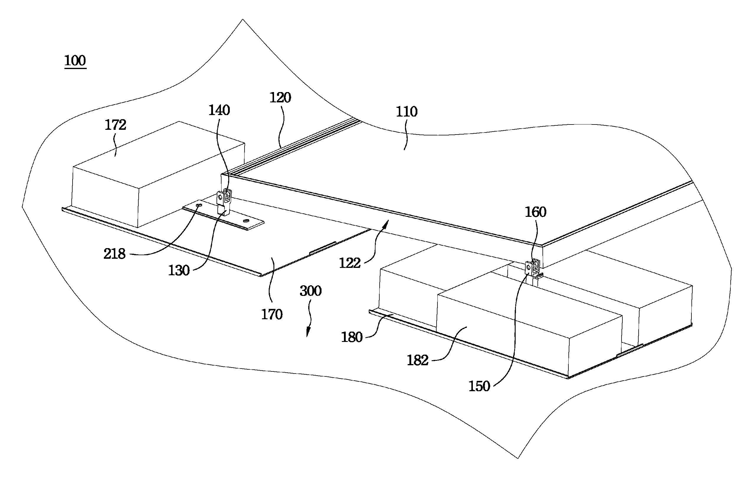
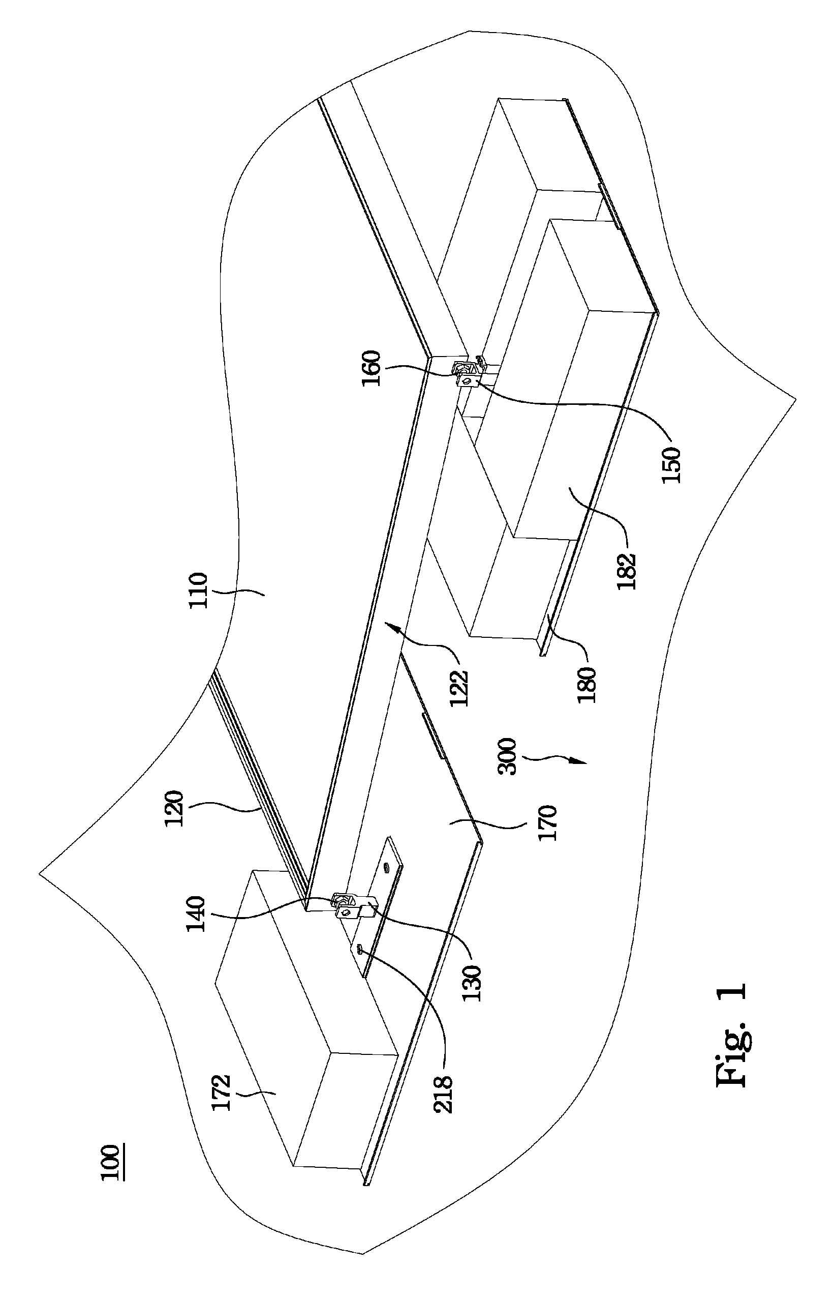
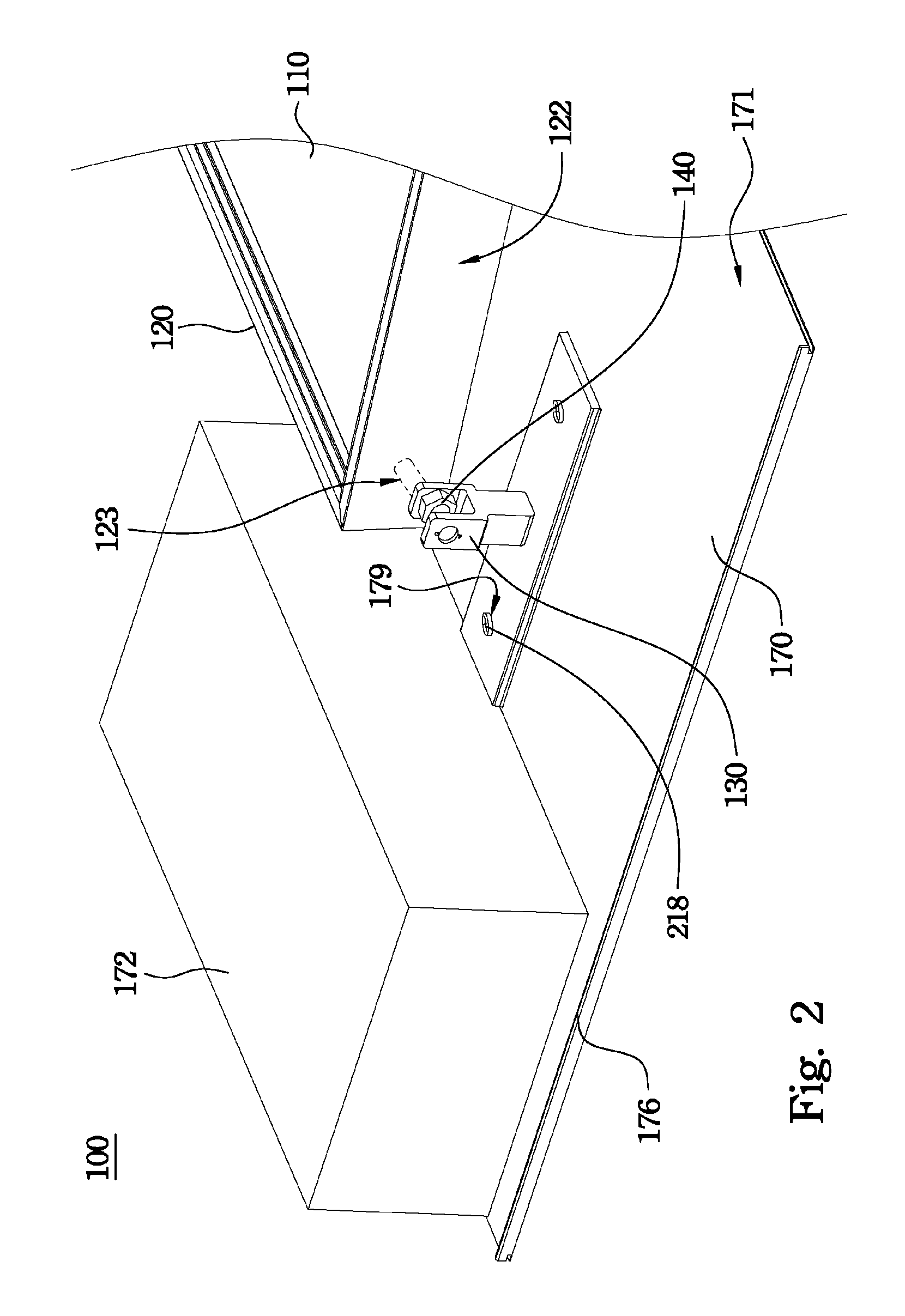
[0031]FIG. 1 is a perspective view of a solar apparatus 100 according to an embodiment of the present invention. As shown in FIG. 1, the solar apparatus 100 includes a solar module and a mounting system thereof. The solar module includes a solar panel 110 and a frame body 120. The mounting system includes a first Y-shaped support 130, a first fixing element 140, a second Y-shaped support 150, and a second fixing element 160. The frame body 120 surrounds an edge of the solar panel 110, and is supported by the first and second Y-shaped supports 130, 150. The frame body 120 is connect...


PUM


Abstract

A solar apparatus includes a solar panel, a frame body surrounding an edge of the solar panel, a first Y-shaped support, and a second Y-shaped support. The first Y-shaped support has two parallel first extending arms and a first supporting portion. The first supporting portion is connected to the two first extending arms, and one of the two first extending arms is fixed on a side of the frame body. The second Y-shaped support has two parallel second extending arms and a second supporting portion. The second supporting portion is connected to the two second extending arms, and one of the two second extending arms is fixed on the side of the frame body. A height of the first Y-shaped support is smaller than a height of the second Y-shaped support.

Description

RELATED APPLICATIONS[0001]This application claims priority to China Application Serial Number 201210337766.X, filed Sep. 13, 2012, which is herein incorporated by reference.BACKGROUND[0002]1. Technical Field[0003]The present disclosure relates to a solar apparatus and a mounting system thereof.[0004]2. Description of Related Art[0005]Solar panels can convert light energy (typically sunlight) into electrical energy without producing any greenhouse gases during the conversion process. Therefore, solar modules are an environmentally friendly way to generate electrical energy.[0006]With the progress and development in photovoltaic technology in recent years, the cost of solar modules has gone down, and this has lead to an increase in the popularity of solar modules in the consumer market. For example, solar modules are now widely used on the rooftops of homes and buildings, as well as in various electronic products.[0007]A conventional solar assembly arranged on a rooftop of a building ...

Claims


Application Information

Patent Timeline
Patent Type & Authority Patents(United States)
IPC IPC(8): E04D13/08H02S20/00
CPCY02B10/12Y02E10/50H01L31/0422H01L31/0484H02S20/00F24J2/4638F24J2/5235H02S20/24F24J2002/5292H02S20/10F24J2/5254F24J2/525F24J2/5211F24S25/15F24S25/20F24S25/617F24S25/632F24S40/85F24S2025/02Y02B10/10Y02E10/47
Inventor KUAN, HAO-HUNGYEN, TUNG-I
Owner AU OPTRONICS CORP
Learn More