
Inertial sensor calibration method for vehicles and device therefor

a technology of inertial sensor and calibration method, which is applied in the direction of vehicle testing, structural/machine measurement, instruments, etc., can solve the problems of low accuracy, low accuracy, and low reliability of inertial sensor calibration devices, etc., and achieves the effect of reducing positioning continuity and reliability

Active Publication Date: 2014-05-20
AUTOMOTIVE RES & TESTING CENT
View PDF2 Cites 9 Cited by
  • Summary
  • Abstract
  • Description
  • Claims
  • Application Information

AI Technical Summary

Benefits of technology

The present invention is an inertial sensor calibration method for vehicles that improves positioning accuracy and reliability. The invention allows the sensor to learn about different road conditions in advance, so that it can calculate variations in vehicle movement based on the current road conditions, even without using GPS or other electronic sensors. This results in real-time vehicle movement data that is used to calibrate the inertial sensor, ensuring constant positioning and reliability. This technology is useful for enhancing the navigation accuracy and reliability of vehicles.

Problems solved by technology

However, those electronic devices used for calibrating errors generated in computation of inertial sensors are sensitive geographically.
For example, satellite signals are lost when the electronic devices pass by high-rise buildings or enter an underground passage, the earth magnetic field strength is relatively weak and the pressure is affected when measured in a tunnel.
Hence, the signals originally serving as reference values for calibration either disappear or become worse in terms of correctness so that the error resulting from the integral computation for the sensed signals of the inertial sensors cannot be lowered.
Accordingly, the electronic device using sensed signals of inertial sensors as control signals fail to provide most adaptive driver assistance when passing through those geographical zones where signals are gone or attenuated.
As far as a navigation system is concerned, the positioning continuity and reliability of the navigation system is both degraded and fails to deliver positioning accuracy when the navigation system passes through an underground passage and fails to smoothly receive satellite signals, and the navigation system may temporarily lose its tracking ability.
As far as an adaptive headlight is concerned, the optimized beam projecting angle or beam shape of the headlight may not be available when the headlight goes through the signal-attenuated zones.

Method used


Image

  • Inertial sensor calibration method for vehicles and device therefor
  • Inertial sensor calibration method for vehicles and device therefor
  • Inertial sensor calibration method for vehicles and device therefor

Examples


Embodiment Construction

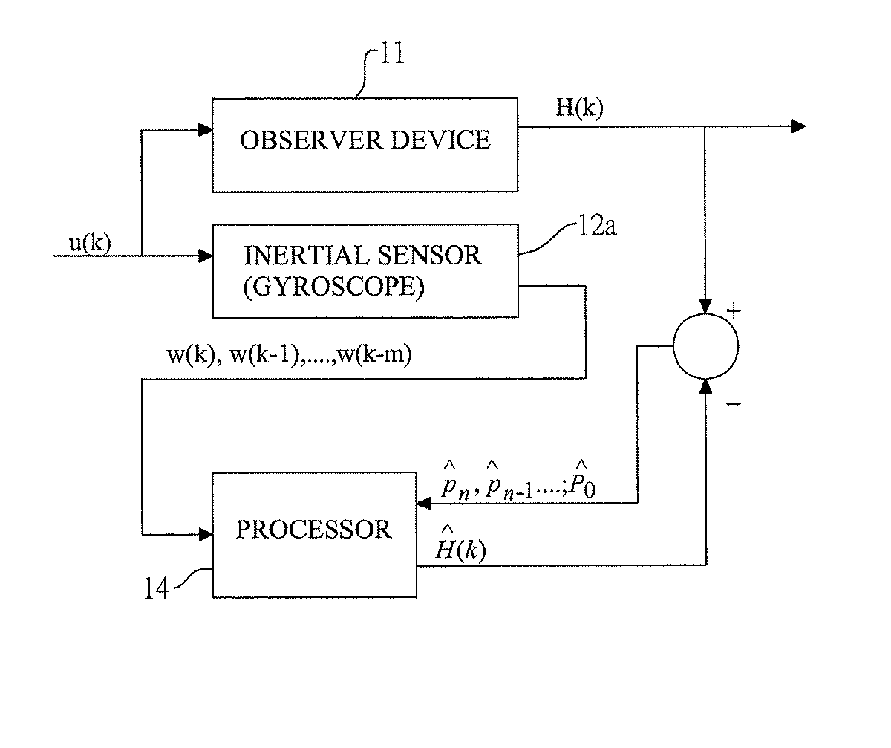
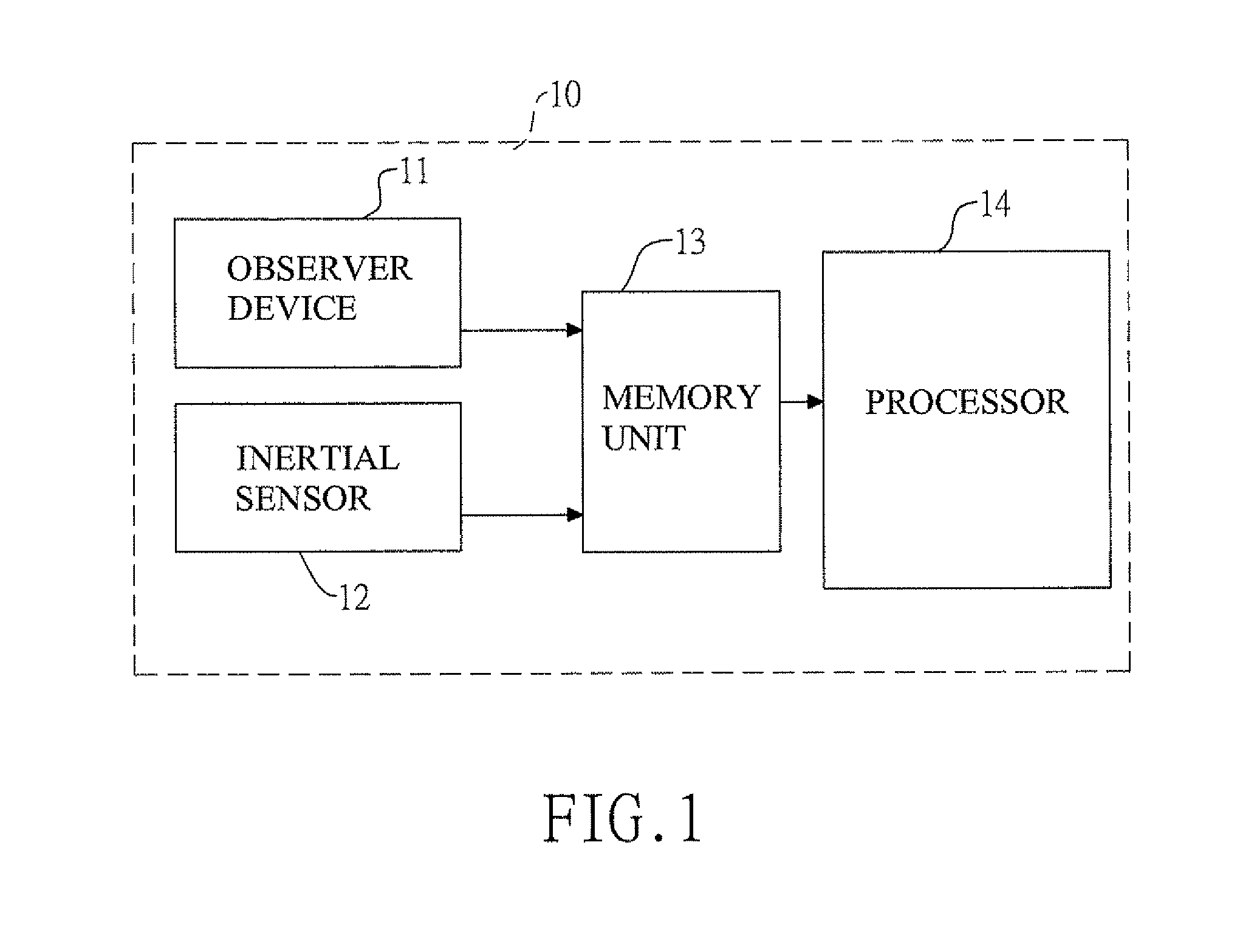
[0028]With reference to FIG. 1, an inertial sensor calibration device 10 for vehicles has an observer device 11, an inertial sensor 12, a memory unit 13 and a processor 14.

[0029]The observer device 11 senses and outputs actual vehicle motion data of a vehicle carrying on an inertial move.

[0030]The inertial sensor 12 senses inertial signal data of the vehicle and outputs the sensed inertial signal data.

[0031]The memory unit 13 is electrically connected to the observer device 11 and the inertial sensor 12 to store the actual vehicle motion data, the sensed inertial signal data and a vehicular dynamic variation model having multiple parameters associated with offset, scale factor and the like.

[0032]The processor 14 is electrically connected to the memory unit 13 and is built in with a learning and calibration procedure for learning actual vehicle motion data associated with various road conditions, calibrating the vehicular dynamic variation model and storing the calibrated vehicular d...


PUM


Abstract

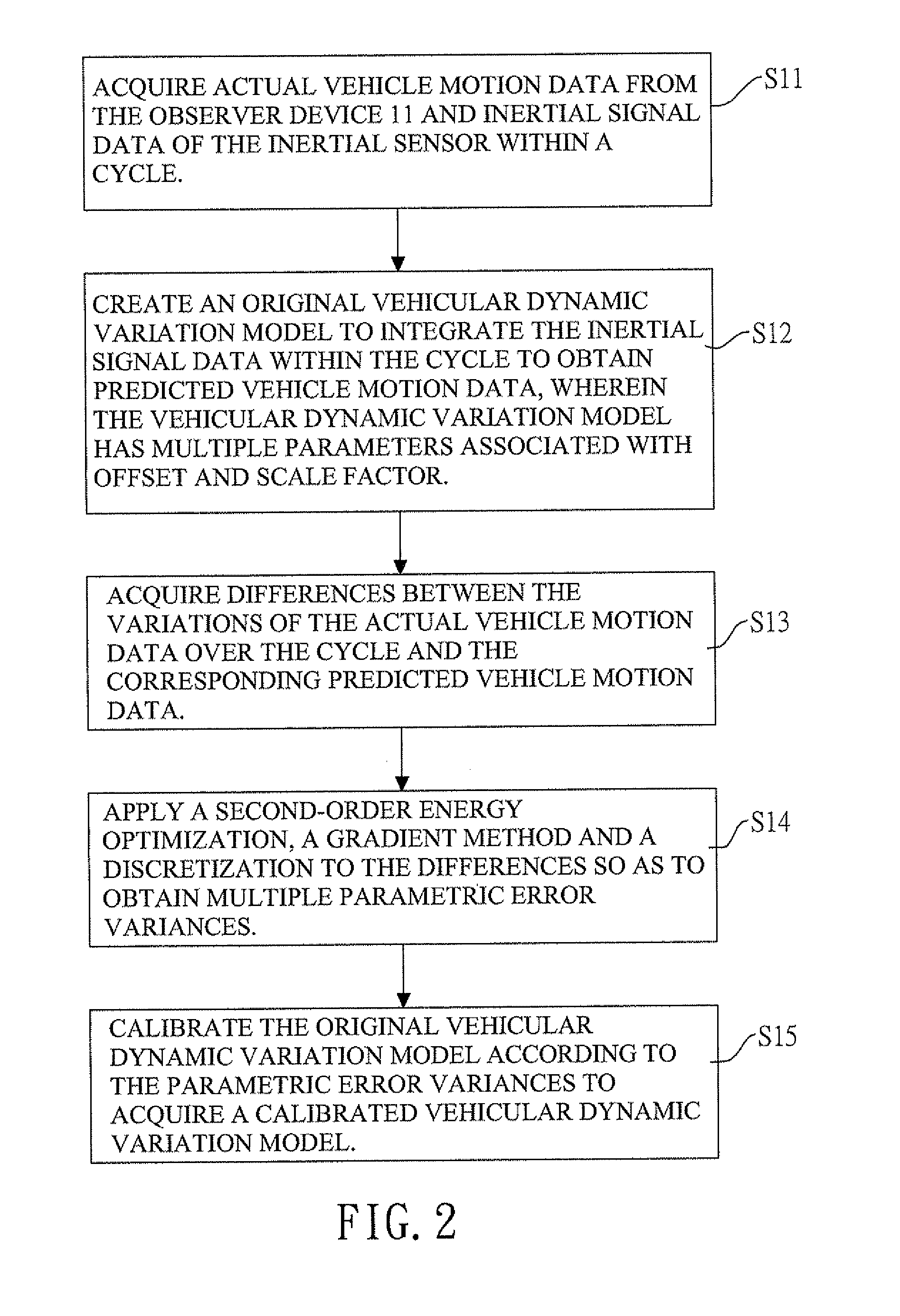
An inertial sensor calibration method has steps of mounting an observer device and an inertial sensor of a vehicle carrying on an inertial move, acquiring actual vehicle motion data from the observer device and inertial signal data of the inertial sensor, calculating an integral corresponding to the vehicular dynamic variation model with respect to the inertial signal data to obtain predicted vehicle sensor data and calculating variations of the actual vehicle motion data, acquiring differences between the two calculated data, applying an energy optimization and a discretization to the differences so as to obtain parametric error variances, and feeding back the parametric error variances to the vehicular dynamic variation model to calibrate the parameters associated with offset and scale factor and acquire a calibrated vehicular dynamic variation model. Under the premise of no GPS, electronic compass or pressure sensor, the present invention can secure positioning continuity and reliability.

Description

BACKGROUND OF THE INVENTION[0001]1. Field of the Invention[0002]The present invention relates to an inertial sensor for vehicles, and more particularly to an inertial sensor calibration method for vehicles and a device therefor.[0003]2. Description of the Related Art[0004]Considering more comfortable and safer driving, many car manufacturers have started building affordable luxury cars equipped with built-in or attached multi-functional electronic devices, such as adaptive headlights, navigation systems, instant traffic alerts and the like, to implement and assist automatic driving.[0005]Most vehicle electronic devices mainly target at assisting drivers to pay attention to or adjust safe driving functions based on instant traffic condition. Given the adaptive headlight as an example, the high beam, low beam and beam shapes thereof can be switched or adjusted in accordance with a driving or road condition when the vehicle makes a turn, goes uphill or goes downhill. Furthermore, a nav...

Claims


Application Information

Patent Timeline
Patent Type & Authority Patents(United States)
IPC IPC(8): G01M17/00
CPCG01C21/16G01C25/005
Inventor HSU, CHAN-WEIKE, LIANG-YU
Owner AUTOMOTIVE RES & TESTING CENT
Learn More