
Vessel for scanning documents

a document scanner and document technology, applied in the field of document scanners, can solve the problems of not being particularly portable, document scanners, etc., and achieve the effect of convenient transportation or storag

Inactive Publication Date: 2014-05-13
MUDD TODD R +1
View PDF9 Cites 0 Cited by
  • Summary
  • Abstract
  • Description
  • Claims
  • Application Information

AI Technical Summary

Benefits of technology

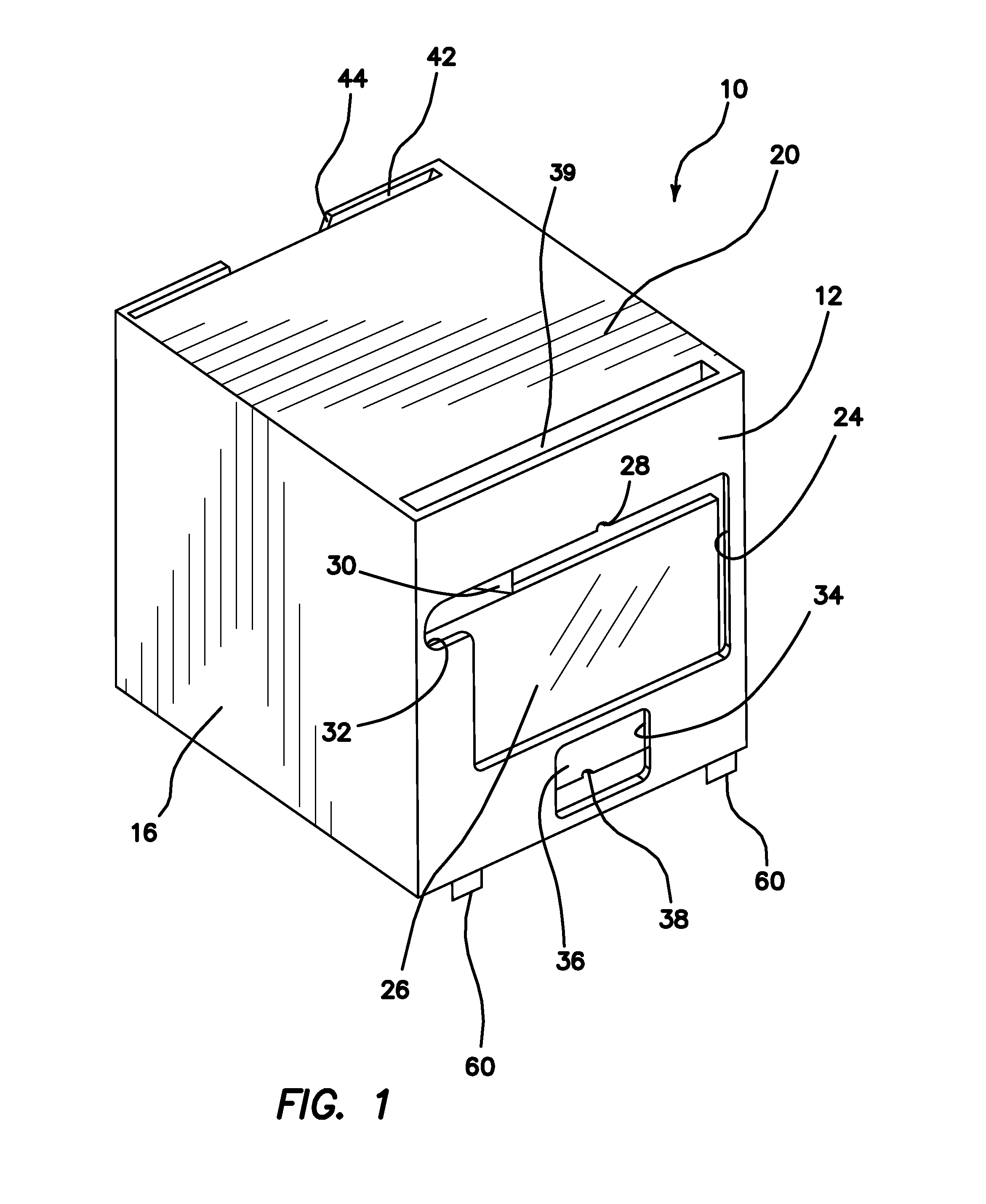
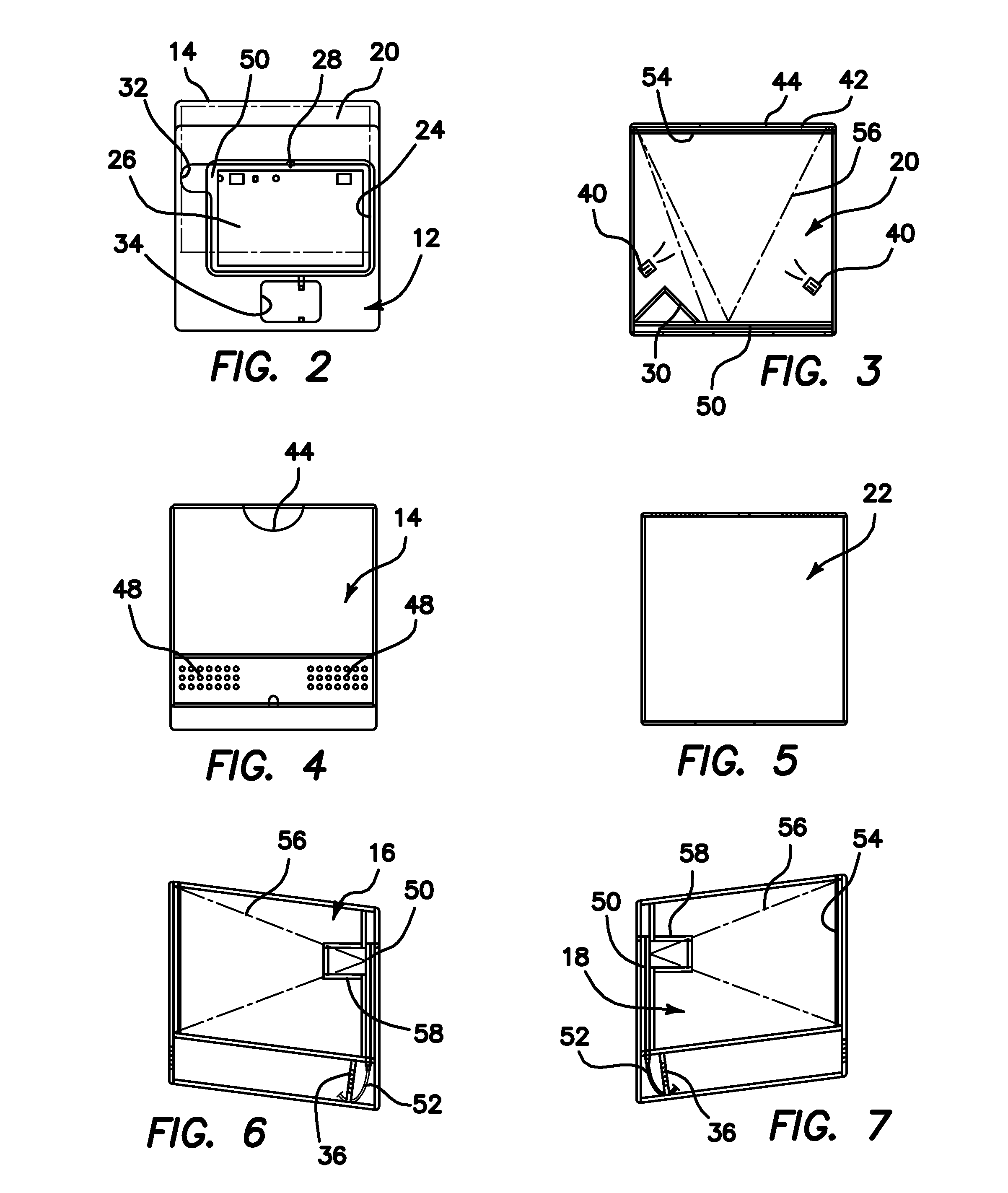
[0003]The present invention addresses the foregoing concerns by providing, in one particular arrangement, a collapsible document scanning device which comprises a docking location for receiving and docking an image capturing device. The device further comprises a document platform spaced from the docking location for receiving a document to be scanned. A structure is provided for supporting each of the docking location and the document platform in spaced relationship to one another in an expanded, operable configuration, wherein the structure comprises a plurality of members which are movable to re-configure the structure from the expanded configuration to a collapsed configuration, in order to render the device inoperable and conveniently transportable or storable. A support plate adjacent to the docking location may be provided for supporting the image capturing device which has been inserted into the docking location.
[0006]In certain embodiments, the structure of the document scanning device comprises a box or case having a front surface panel, a rear surface panel, a left surface panel, a right surface panel, a top surface panel, and a bottom surface panel, wherein the movable members comprise portions of some of the panels. In other embodiments, the structure is constructed to be open in the expanded configuration and the document platform comprises one of the movable members. In some of the open embodiments, the device further comprises movable support pillars for supporting the docking location in spaced relationship to the document platform in the expanded configuration. In others, hinges having stop points eliminate the need for such support pillars.
[0010]For the enclosed embodiments, artificial lighting may be provided in the interior cavity for enhancing the scanning function.
[0011]In still another aspect of the invention, there is provided a method of scanning a document using a document scanning device comprising a case which defines a cavity and has a docking location on a first side and a document platform on a second opposed side thereof. The inventive method comprises steps of inserting an electronic image capturing device into the docking location, inserting a document to be scanned onto the document platform, activating a camera on the electronic image capturing device, and capturing an image of the document. If an enclosed embodiment is being utilized, the inventive method may further comprise a step of lighting the cavity to improve the image quality. Once the document image has been captured, the method may also comprise a further step of transmitting the image to another location, using a communications network.
[0012]Additionally, in certain embodiments, the inventive method may also comprise a step of detaching a first docking location having a first configuration for accommodating an image capturing device having a first particular configuration, and then attaching a second docking location having a second configuration for accommodating an image capturing device having a second particular configuration. By providing a variety of differently configured detachable docking locations, customized to different available image capturing devices, the inventive system may be effectively utilized with most or all of those devices, in an optimal way.

Problems solved by technology

Document scanners are well known for this purpose, but they are not particularly portable.

Method used


Image

  • Vessel for scanning documents
  • Vessel for scanning documents
  • Vessel for scanning documents

Examples


second embodiment

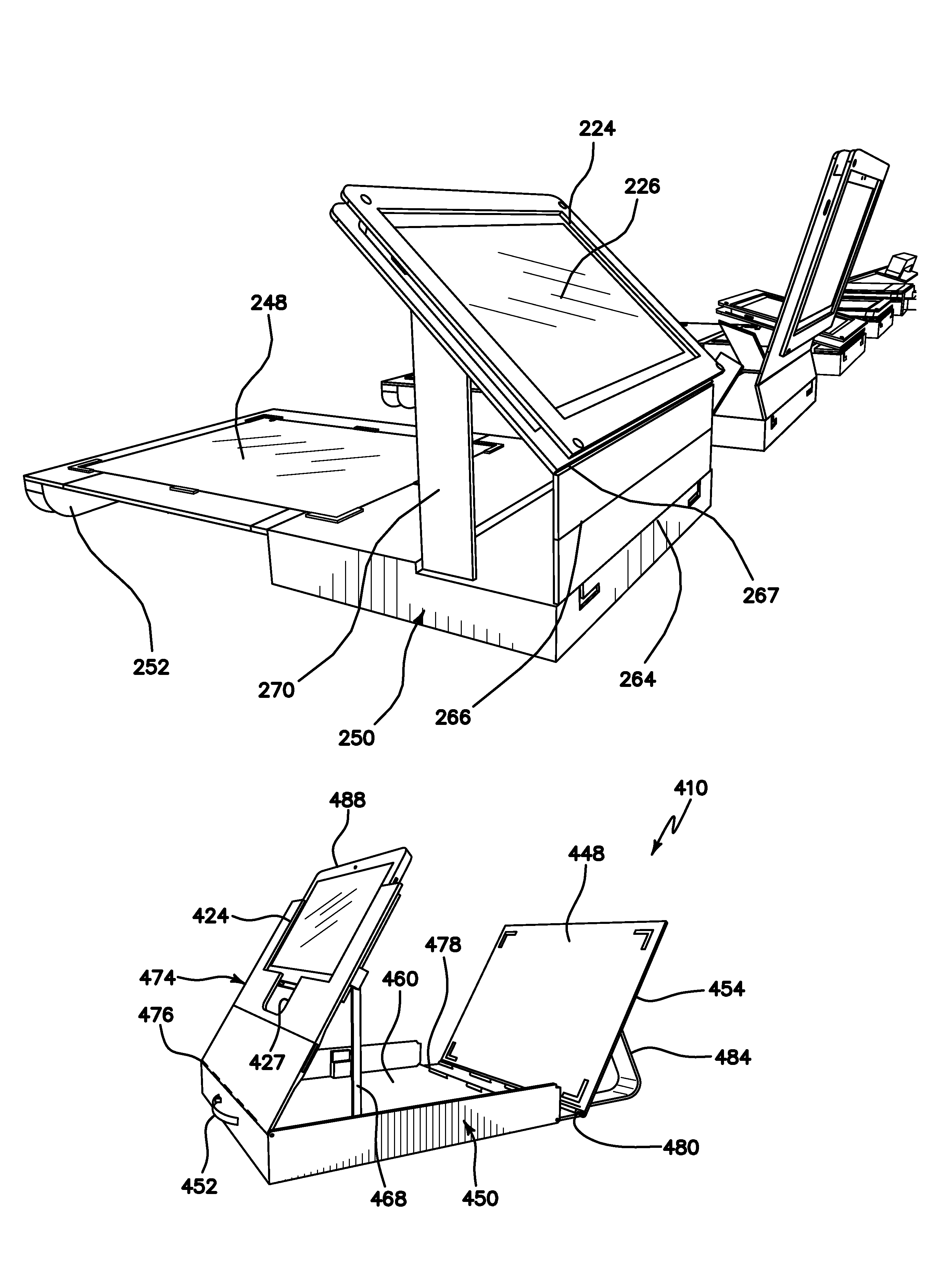
[0057]A third modified embodiment of the document scanning device 210 of the present invention is illustrated in FIGS. 13-18, wherein common elements to those in the second embodiment are identified by common reference numerals, preceded by the numeral “2”, rather than “1”. One difference between this embodiment and that of FIGS. 8-12 is that the FIGS. 8-12 embodiment is particularly suitable for low-light environments, because lighting may be provided within the device 110. In the FIGS. 13-18 embodiment, adequate ambient lighting is assumed, partially because of its open construction, so no artificial light source is provided.

[0058]In FIG. 13, the device 210 is shown in its open, operational configuration. The device 210 includes a docking location 224 with a support plate 226 for accommodating a desired imaging device having a camera for imaging a document. The document to be imaged is placed on a document platform 248. The device is arranged so that the docking location 224 is di...

embodiment 310

[0064]FIGS. 19-23 illustrate yet another embodiment 310 of the present invention, which bears a similarity particularly to the embodiment of FIGS. 13-18. In this embodiment, common elements to those in the previous embodiments shown in FIGS. 8-18 are identified by common reference numerals, preceded by the numeral “3”.

[0065]In this embodiment 310, there are provided a lower portion 372 and an upper portion 374, shown in its collapsed orientation, whereby the upper portion 374 is folded to lie atop the lower portion 372 about a hinge 376. The docking location 324 and support plate 326 are disposed in the upper portion 374. A tablet accessory cut-out 327, like tablet accessory cut-out 34 of FIG. 1, is also provided.

[0066]As shown in FIG. 20, when the device 310 is in an expanded configuration (left-most figure), the upper portion 374 is oriented toward the vertical direction, pivoted about the hinge 376, so that it is spaced from the lower portion 372. In this open orientation, a docu...

embodiment 410

[0072]A significant feature of the embodiment 410 is that the docking location 424 for accommodating a tablet personal computer / imaging device 488 having a camera 490 comprises a detachable faceplate, rather than a built-in fixed member as in the other embodiments. In this embodiment, a plurality of such detachable faceplates 424 are available, each customized to accommodate a particular brand or model of tablet p.c. or imaging device 488 and its unique camera location and orientation, to ensure an optimal viewing angle between the camera 490 and the document platform 448. It is noted that each of the prior embodiments 110, 210, 310 could similarly be modified to incorporate a detachable faceplate, customized to optimize imaging from a particular imaging device, if desired.

[0073]It should be noted that an auto-document feeder may optionally be included in all embodiments, if desired.

[0074]In all of the foregoing embodiments having hinges, the described hinges may be of any known typ...


PUM


Abstract

A method of scanning a document uses a document scanning device having a case which defines a cavity and has a docking location on a first side and a document platform on a second opposed side. The method includes steps of inserting an electronic image capturing device into the docking location, inserting a document to be scanned onto the document platform, activating a camera on the electronic image capturing device, and capturing an image of the document. Once the document image has been captured, the method may also include a further step of transmitting the image to another location, using a communications network.

Description

[0001]This application claims the benefit under 35 U.S.C. 119(e) of the filing date of Provisional U.S. Application Ser. No. 61 / 538,452, entitled Vessel for Scanning Documents, filed on Sep. 23, 2011, and also claims the benefit under 35 U.S.C. 119(e) of the filing date of Provisional U.S. Application Ser. No. 61 / 587,109, entitled Vessel for Scanning Documents, filed on Jan. 16, 2012. Both of these provisional applications are expressly incorporated herein by reference, in their entirety.BACKGROUND OF THE INVENTION[0002]Frequently, during the course of modern business, it is necessary to scan documents for electronic transmittal and / or storage. Document scanners are well known for this purpose, but they are not particularly portable. Therefore, it would be advantageous to be able to effectively use portable camera technology, such as that available in modern smart phones and tablet-style personal computers (tablet p.c.), to reliably and quickly scan documents.SUMMARY OF THE INVENTIO...

Claims


Application Information

Patent Timeline
Patent Type & Authority Patents(United States)
IPC IPC(8): H04N1/04
CPCH04N1/00541H04N1/00307H04N2201/045H04N1/00535H04N1/04
Inventor MUDD, TODD R.PERCIVAL, NICHOLAS A.
Owner MUDD TODD R
Learn More