Multiple oven

a multi-oven technology, applied in the field of multi-ovens, can solve the problems of insufficient implementation of explicit separation of air containing vapor from air containing no vapor, too large outlet for effective extraction, etc., and achieve the effect of saving construction costs

Inactive Publication Date: 2014-04-29
BSH BOSCH & SIEMENS HAUSGERAETE GMBH
View PDF13 Cites 25 Cited by
  • Summary
  • Abstract
  • Description
  • Claims
  • Application Information

AI Technical Summary

Benefits of technology

[0004]The object of the present invention is thus to create an option for simplified embodiment of a ventilation area of a multiple oven, especially of a double oven. Advantageously an option is to be created for constructively-simple separation of exhaust air containing vapor and exhaust air not containing vapor and / or for a simplification of the construction of the individual devices.
[0005]To this end the multiple oven, especially a double oven, with at least one lower oven and an upper oven arranged above it, features an upper fan for sucking in air over a surface of the upper oven, which in its turn features an upper vapor outlet, and also a lower fan for sucking in air over a surface of the lower oven, which features a lower vapor outlet. The multiple oven further features at least one vapor suction duct for directing vapor exiting from one of the vapor outlets to one of the associated fans. The vapor suction duct makes it possible to decouple the position of fan and associated vapor outlet and thus to obtain a simplification of the construction of the individual devices as such. The vapor suction duct also allows air containing vapor to be separated from air not containing vapor en route to the fan in a constructively simple and effective manner.
[0006]It is advantageous for the constructively simple and low-cost structure of the individual devices for both vapor outlets to be arranged on the same side of the respective surface (especially on the left or the right hand side of the upper side of the oven), and for the fans to be offset to the side in relation to each other. The vapor suction duct can then be present as a ventilation bridge which is configured to direct vapor sideways to the associated fan.
[0007]It is also advantageous for the fan associated with the vapor suction duct (which is connected in terms of flow by the vapor suction duct to the vapor outlet) to be embodied so that air containing vapor sucked into a part area of the fan assigned to the vapor suction duct and air not containing vapor sucked into another part area of the fan are not mixed air in the fan. To this end it is especially advantageous for a crossflow fan to be used as the fan, since this can keep the incoming air flows separated without further separation devices.
[0012]It is frequently advantageous and sufficient for only one of the fans to be assigned a vapor suction duct, which saves construction costs.

Problems solved by technology

The fact that the fans are offset to the side means that the vapor outlets must also be offset accordingly, since otherwise the distance between at least one of the fans and the assigned vapor outlet is too large for a effective extraction of the vapor.
However with known solutions the explicit separation of air containing vapor from air containing no vapor has to date only been inadequately implemented using solutions which are simple in their construction.

Method used


Image

  • Multiple oven
  • Multiple oven

Examples


Embodiment Construction

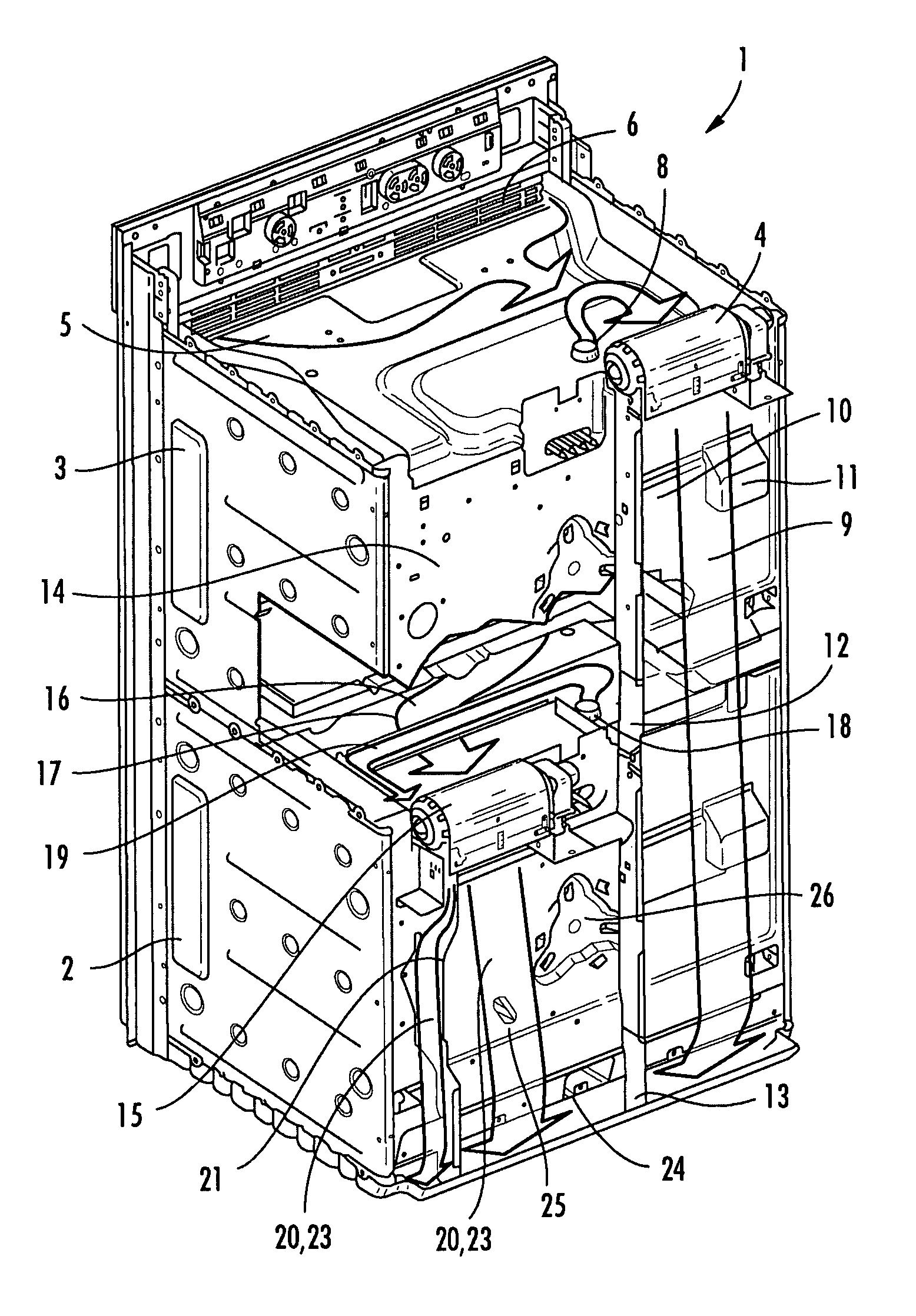
[0014]A double oven 1, which is shown without the built-in housing, features a lower oven 2 and an upper oven 3 arranged above it. At a rear edge area of the upper oven 3 an upper fan 4 in the form of a crossflow fan is arranged so as to enable it suck in fresh air 5, as indicated by the arrow shape, through a front ventilation grid 6 via an upper side [7] of the upper oven 3. Incorporated into the upper side [7] is an upper vapor outlet 8 through which vapor can be extracted from the oven space (not shown). Vapor exiting from the vapor outlet 8 is likewise sucked in by the upper fan 4, as indicated by the associated arrow. So that the vapor is completely sucked in where possible, the vapor outlet 8 is provided in the lower right-hand area of the upper side [7] of the upper oven 3, and the upper fan 4 is located for this purpose at a short distance from the edge area lying immediately behind it. From the upper fan 4 mixed air containing vapor is taken out through a first exhaust duc...


PUM


Abstract

A multiple oven, especially a double oven, with at least one lower oven and an upper oven arranged above it, features an upper fan for sucking in air over a surface of the upper oven, which features an upper vapor outlet, and also a lower fan for sucking in air over a surface of the lower oven, which features a lower vapor outlet. The multiple oven further features at least one vapor suction duct which is present for directing vapor exiting from the vapor outlet to one of the associated fans.

Description

BACKGROUND OF THE INVENTION[0001]Double ovens, comprising ovens or oven cavities arranged one above the other are known, in which each of the ovens features a fan for sucking in air over its upper side, with a vapor outlet being inserted into the upper side in each case. Typically fresh air is sucked in from the front over the upper side to a fan mounted at the rear, and then from there as exhaust air containing vapor along the rear of the double oven in a floor area and onwards through the floor area to a front-side oven exhaust air opening.[0002]Since the fans occupy a comparatively large volume, they are arranged (when viewed from the rear) offset to the side, so that the lower fan does not reduce the flow cross section of an exhaust air duct of an upper fan too much. The then likewise offset exhaust air ducts of upper fan and lower fan merge back into each other in the floor area. The fact that the fans are offset to the side means that the vapor outlets must also be offset acco...

Claims


Application Information

Patent Timeline
Patent Type & Authority Patents(United States)
IPC IPC(8): F24C15/32
CPCF24C15/2007F24C15/006
Inventor HASSLBERGER, ROBERTHOFMANN, JOHANNMEISINGER, CHRISTIANROSENBAUER, JORGSCHUCHHARDT, JURGENTHEINE, MARKUS
Owner BSH BOSCH & SIEMENS HAUSGERAETE GMBH
Why Eureka
Try Eureka