
Electronic flight bag mounting system

a technology of mounting system and flight bag, which is applied in the direction of machine supports, curtain suspension devices, electric apparatus casings/cabinets/drawers, etc., can solve the problems affecting the ability of the pilot, and achieve the effect of reducing the obstruction of the pilot's view, good pilot's view, and high level of situational awareness

Active Publication Date: 2014-04-22
VERTEX AEROSPACE LLC
View PDF28 Cites 14 Cited by
  • Summary
  • Abstract
  • Description
  • Claims
  • Application Information

AI Technical Summary

Benefits of technology

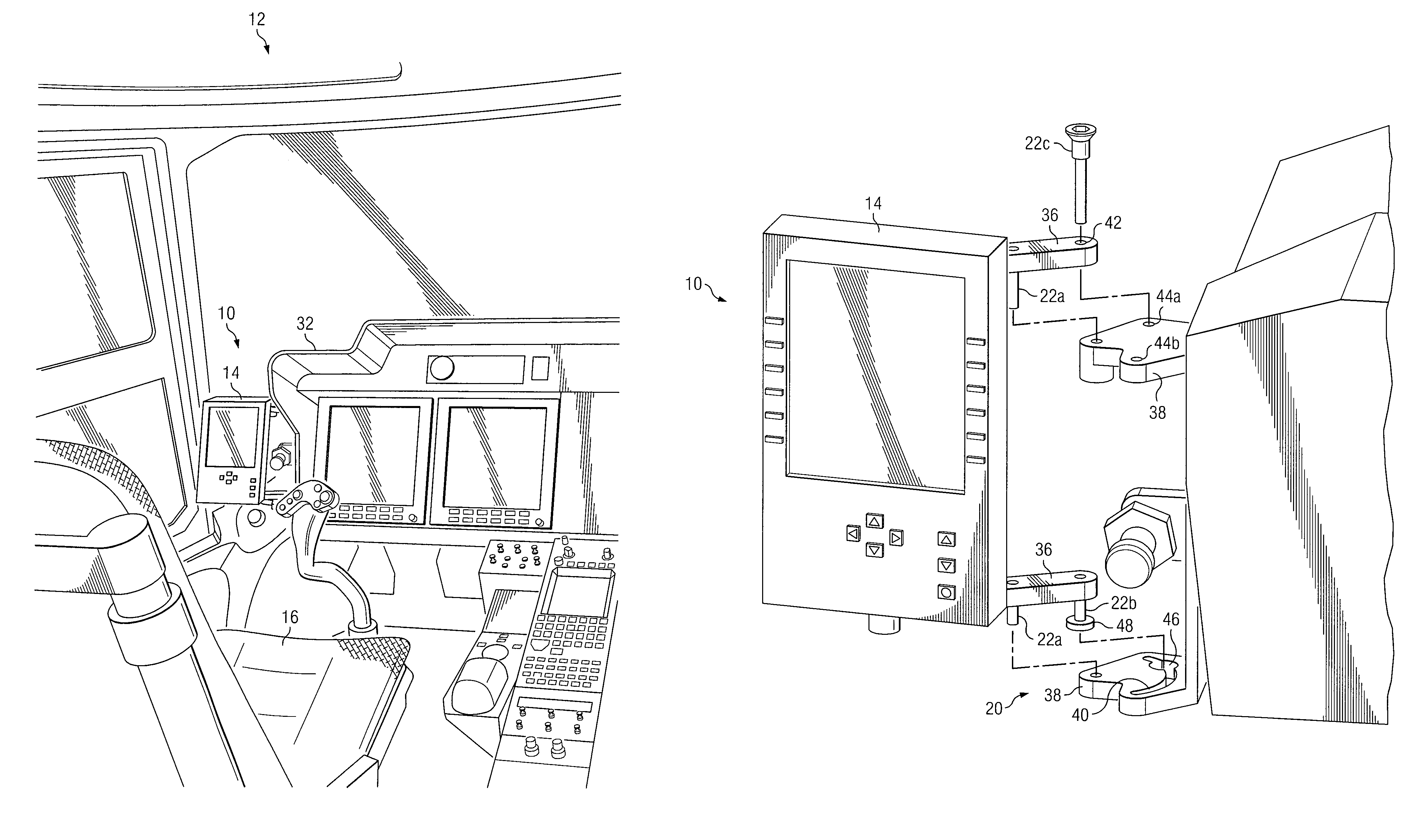
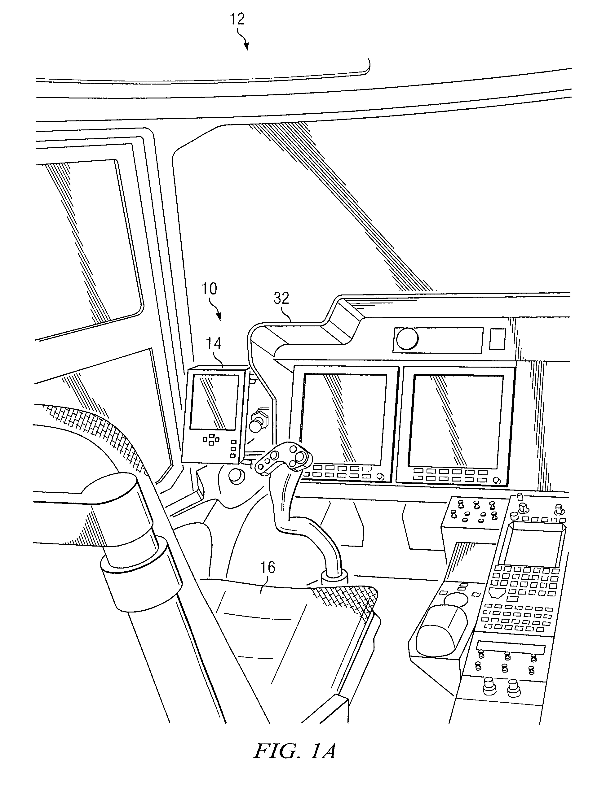
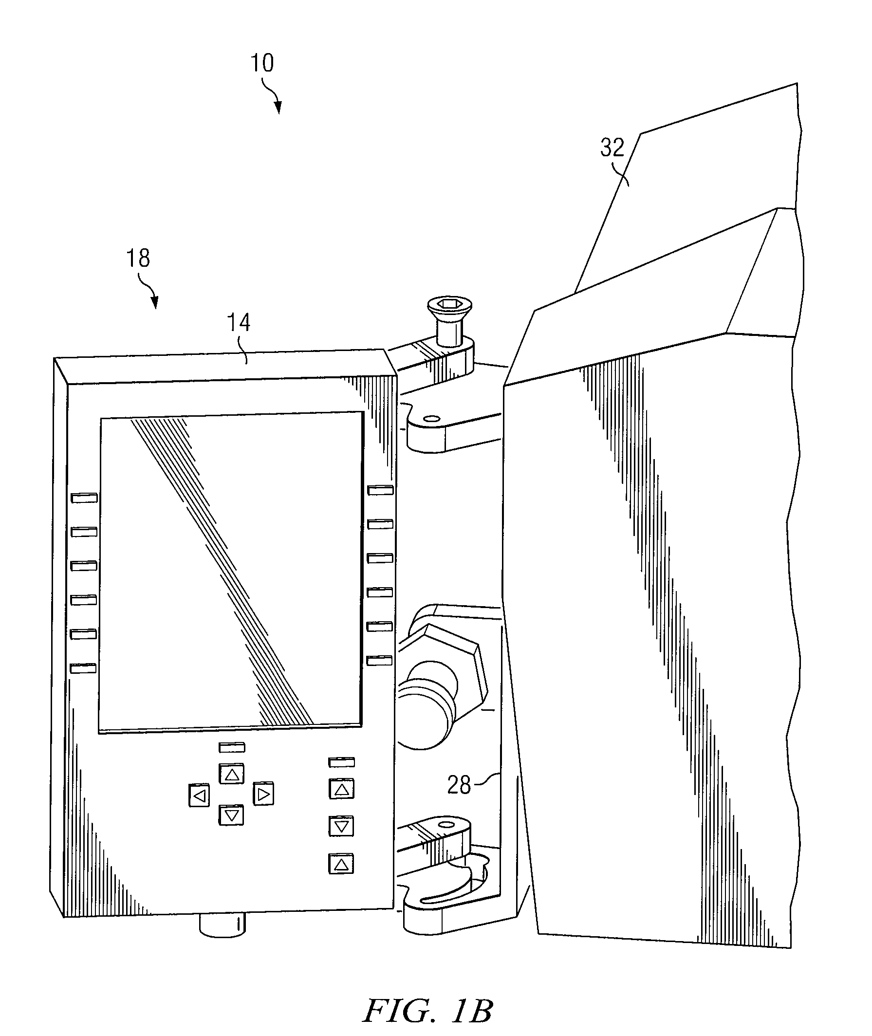
[0006]Some embodiments of the disclosure may provide numerous technical advantages. For example, one embodiment of the electronic flight bag mounting system may maintain the electronic flight bag in an easily viewed location in the cockpit of an aircraft, and provides for its movement to a storage position that may reduce obstruction of the pilot's view when not in use. Cockpits of aircraft are often configured with many instruments and control mechanisms that may be positioned in the cockpit to provide relatively good view for the pilot while operating the aircraft. In many cases, the placement of these instruments and control mechanisms may affect the ability of the pilot to react in a timely manner to changing conditions of the aircraft and other external elements affecting operation of the aircraft. The electronic flight bag mounting system according to the teachings of the present disclosure provides a relatively high level of situational awareness for the pilot by allowing a good ergonomic view of the electronic flight bag when needed, and providing a storage position for the electronic flight bag that does not unduly obstruct his or her view when not needed.

Problems solved by technology

In many cases, the placement of these instruments and control mechanisms may affect the ability of the pilot to react in a timely manner to changing conditions of the aircraft and other external elements affecting operation of the aircraft.

Method used


Image

  • Electronic flight bag mounting system
  • Electronic flight bag mounting system
  • Electronic flight bag mounting system

Examples


Embodiment Construction

[0012]It should be understood at the outset that, although example implementations of embodiments are illustrated below, various embodiments may be implemented using any number of techniques, whether currently known or not. The present disclosure should in no way be limited to the example implementations, drawings, and techniques illustrated below. Additionally, the drawings are not necessarily drawn to scale.

[0013]Electronic flight bags (EFBs) are computing devices that perform functionality associated with operation of an aircraft. For example, electronic flight bags may include navigational charts to aid its user with the development of flight plans. These electronic flight bags may also include various tools for calculating other operational parameters of the aircraft's flight including the minimum amount of fuel needed, takeoff speed, and / or specific routes to be taken.

[0014]Electronic flight bags are often housed in relatively small tablet-sized housings that may be easily car...


PUM


Abstract

According to one embodiment, an electronic flight bag mounting system a cockpit mounting member coupled to an electronic flight bag mounting member. The cockpit mounting member is configured to mount to a cockpit of an aircraft, while the electronic flight bag mounting member is configured to be coupled to an electronic flight bag. The electronic flight bag mounting member is movable from a deployed position in which a display of the electronic flight bag faces a cockpit seat configured in the cockpit to a storage position in which the electronic flight bag faces away from the cockpit seat.

Description

GOVERNMENT RIGHTS[0001]This invention was made with government support under government contract number N00019-05-G-0008, MV-22 Netted Weather Trade Study. The Government may have certain rights in this invention.TECHNICAL FIELD OF THE DISCLOSURE[0002]This disclosure generally relates to electronic flight bags, and more particularly, to an electronic flight bag mounting system and a method of using the same.BACKGROUND OF THE DISCLOSURE[0003]The operation of aircraft often entails numerous management operations to ensure its safe operation during flight. Management operations may include pre-flight check procedures to verify operational integrity of the aircraft, generation of flight plans detailing specific routes to be taken, and / or take off or landing calculations based upon the capability of the aircraft and its intended payload.[0004]Historically, management operations related to the operation of aircraft have been conducted using paper-based forms and logbooks in which entries ...

Claims


Application Information

Patent Timeline
Patent Type & Authority Patents(United States)
IPC IPC(8): B60R9/00B60R11/00A47H1/10A47F5/00E04G3/00
CPCB64D45/00B60R11/0252B60R2011/0005B60R2011/0052B64D2045/0075B60R2011/0085H05K5/0226B60R2011/0082
Inventor BOPP, JAYSON K.PALMER, SARAH L.
Owner VERTEX AEROSPACE LLC
Learn More