
Golf club head with variable face thickness

a golf club head and variable technology, applied in the field of golf club head with variable face thickness, can solve the problems of physical and practical limitations, adversely affecting the performance of the golf club, and limited design of the conventional golf club head with regard to the maximum face area

Active Publication Date: 2014-04-15
TOPGOLF CALLAWAY BRANDS CORP
View PDF12 Cites 59 Cited by
  • Summary
  • Abstract
  • Description
  • Claims
  • Application Information

AI Technical Summary

Benefits of technology

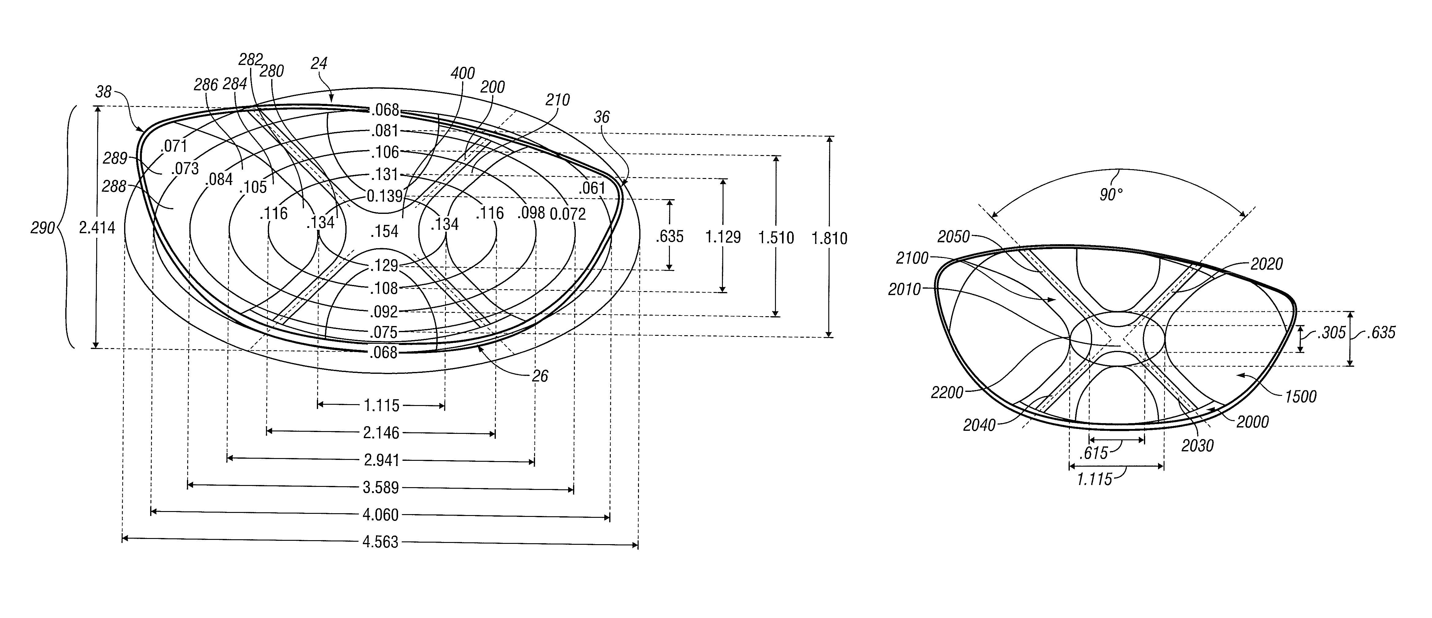
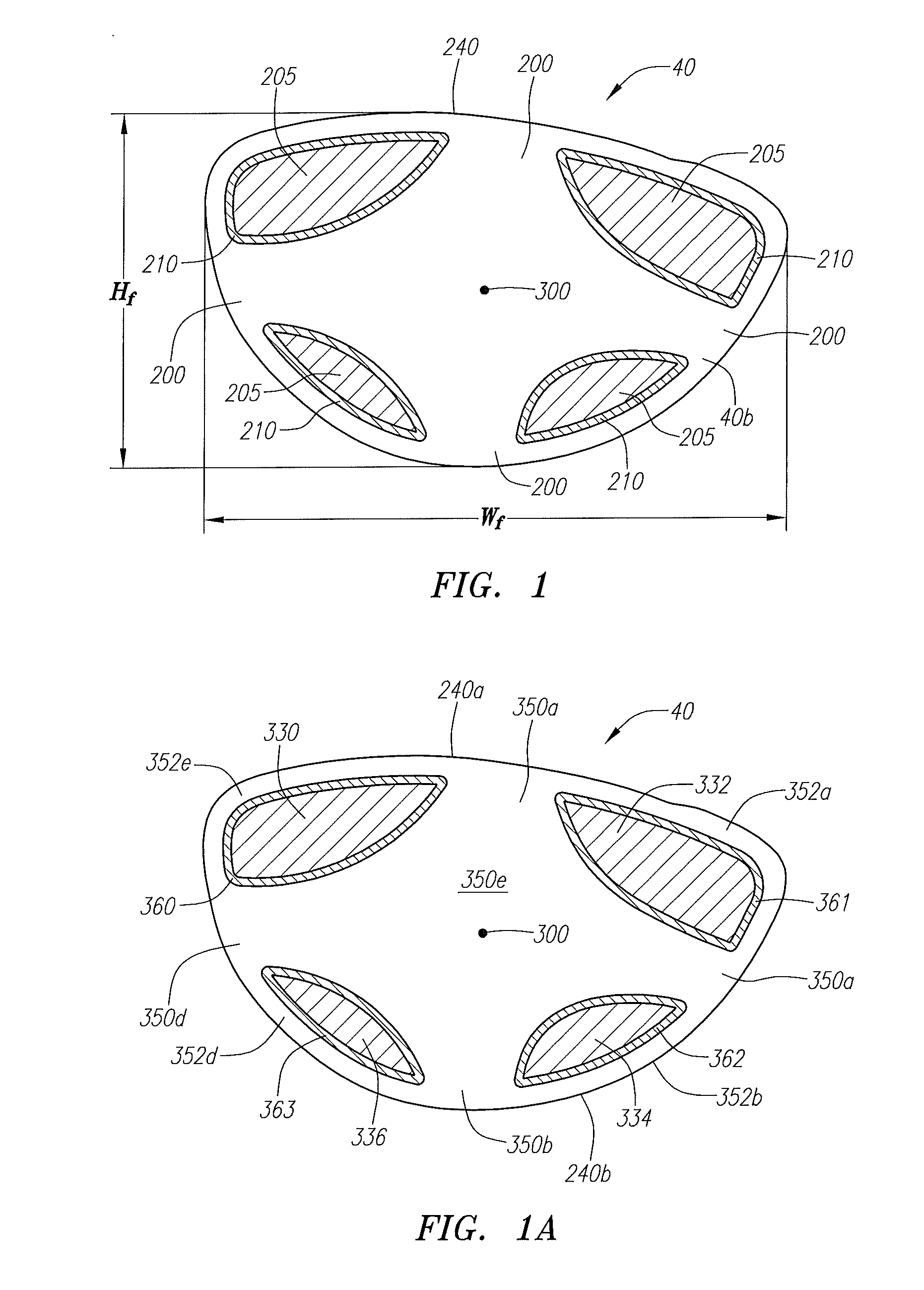
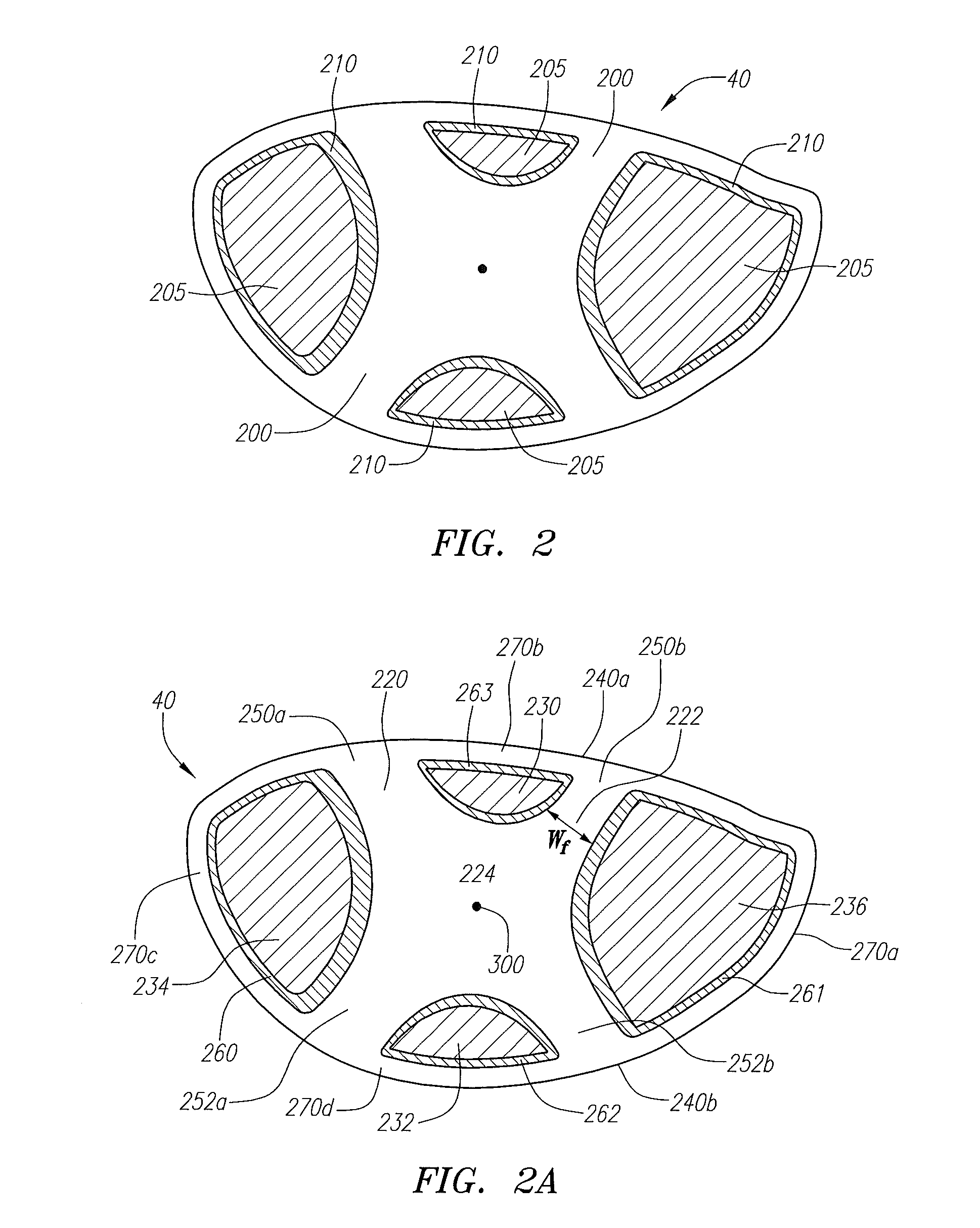
[0014]The present invention is directed at a face with variable thickness that allows for a lightweight face or face insert that conforms to the USGA characteristic time test. The present invention is able to accomplish this by providing an interior surface that comprises at least a first thickness section and a second thickness region.

Problems solved by technology

Conventional golf club head designs are limited with regard to the maximum face area, both physical and practical limitations.
The physical limitation is due to the golf club head having insufficient mass to both increase the length and width of the golf club head and also to increase the face size without exceeding the upper range of the preferred total golf club head mass.
Further, the thinning of the face thickness of a large face area golf club head will result in a golf club head that does not conform with the United States Golf Association's “Pendulum Test” which measures the characteristic time of the golf club head.
However, the addition of such a large amount of material to a face generally adversely affects the performance of the golf club.
However, the prior art has failed to design a face or face plate that varies the thickness according to predicted golf ball impact points on the face.

Method used


Image

  • Golf club head with variable face thickness
  • Golf club head with variable face thickness
  • Golf club head with variable face thickness

Examples


second embodiment

[0098]the golf club head 20 is shown in FIGS. 13-15, such as disclosed in U.S. Pat. No. 6,565,452, for a Multiple Material Golf Club Head with Face Insert, filed on Feb. 28, 2002, and is hereby incorporated by reference in its entirety. In this embodiment, the golf club head 20, a face component 60 and an aft-body 61. The face component 60 has a face cup and has a separate face insert 40, which is placed within an opening 45 of a face cup 74. The aft-body 61 has a crown portion 62 and a sole portion 64.

[0099]The face cup 74 has a return portion 63 that extends laterally rearward from the perimeter 73 of the front wall. The face insert 40 is joined to the face cup 74 of the face component 60 in a manufacturing process discussed in co-pending U.S. application Ser. No. 10 / 710,143, entitled Method for Processing a Golf Club Head with Cup Shaped Face Component, filed on Jun. 22, 2004, and hereby incorporated by reference in its entirety.

[0100]The return portion 63 of the face cup prefera...

third embodiment

[0110]the golf club head 20 is shown in FIGS. 16-18. In this embodiment, the golf club head 20 includes a body 22, a face 40 a weighting frame 42, and an optional support gasket 44. A more thorough description of such a golf club head 20 is set forth in U.S. Pat. No. 6,672,975, for a Golf Club Head, and assigned to the assignee of the present application, and which is hereby incorporated by reference in its entirety.

[0111]The body 22 is preferably composed of a light weight or low-density material, preferably a non-metal material or a low-density (less than 4.5 grams per cubic centimeter) metal material, such as a polycarbonate material. Other materials for the body 22 include a composite material such as a continuous fiber pre-preg material (including thermosetting materials or a thermoplastic material for the resin), other thermosetting materials such as thermosetting polyurethane, or other thermoplastic materials such as polyamides, polyimides, polycarbonates, PBT (Polybutlene Te...


PUM


Abstract

A face for a golf club head is disclosed herein. The face has an interior surface comprising a central region having a first perimeter having an elliptical shape, an outer edge having a non-elliptical, driver-face profile shape, a first intermediate region located between the first perimeter and the outer edge, the first intermediate region having a second perimeter with a shape that is more similar to the shape of the first perimeter than the shape of the outer edge, and a second intermediate region located between the second perimeter and the outer edge, the second intermediate region having a third perimeter with a shape that is more like the shape of the outer edge than the shape of the first perimeter. The thicknesses of the perimeters of the face disclosed herein may vary around their respective circumferences.

Description

CROSS REFERENCES TO RELATED APPLICATIONS[0001]The present application is a continuation-in-part application of U.S. patent application Ser. No. 13 / 220,287, filed on Aug. 29, 2011, which is a continuation application of U.S. patent application Ser. No. 12 / 711,435, filed on Feb. 24, 2010, now U.S. Pat. No. 8,012,041, which claims priority under 35 U.S.C. §119 to U.S. Provisional Patent Application No. 61 / 305,844, filed on Feb. 18, 2010, and claims priority under 35 U.S.C. §120 as a continuation-in-part application of U.S. patent application Ser. No. 12 / 268,181, filed on Nov. 10, 2008, now U.S. Pat. No. 7,713,140, which is a continuation application of U.S. patent application Ser. No. 11 / 928,318, filed on Oct. 30, 2007, now U.S. Pat. No. 7,448,960, which is a continuation application of U.S. patent application Ser. No. 11 / 841,384, filed on Aug. 20, 2007, now U.S. Pat. No. 7,422,528, which is a continuation application of U.S. patent application Ser. No. 11 / 469,742, filed on Sep. 1, 200...

Claims


Application Information

Patent Timeline
Patent Type & Authority Patents(United States)
IPC IPC(8): A63B53/04
CPCA63B53/0466A63B2053/045A63B2053/0412A63B2053/0416A63B2053/0491A63B2053/0408A63B53/02A63B53/04A63B2053/0458A63B53/0408A63B53/0412A63B53/0416A63B53/045A63B53/0458A63B60/00
Inventor GIBBS, EVAN D.HALL, J. NEILRICHARDSON, WILLIAM D.TANG, LARRY G.AGUINALDO, HOMER E.
Owner TOPGOLF CALLAWAY BRANDS CORP
Learn More