
Representative image display device and representative image selection method

Active Publication Date: 2014-03-25
AT&T MOBILITY II LLC +1
View PDF14 Cites 9 Cited by
  • Summary
  • Abstract
  • Description
  • Claims
  • Application Information

AI Technical Summary

Benefits of technology

The present invention provides an image display device and method that allows users to efficiently annotate results from image grouping. By displaying likelihood results alongside images, users can quickly identify and separate inaccurately grouped images. This results in a more accurate and efficient process of annotating images.

Problems solved by technology

Despite this fact, none of the above-described conventional techniques takes into consideration how such a representative facial image to be displayed is selected.
Hence, the above-described conventional techniques give rise to the problem that, because facial images that the user need to correct are not displayed, the user cannot perform efficient annotation on the result of facial image clustering.
The same problem occurs in a case where the user performs annotation on the result of clustering of images other than facial images.

Method used


Image

  • Representative image display device and representative image selection method
  • Representative image display device and representative image selection method
  • Representative image display device and representative image selection method

Examples


first embodiment

[First Embodiment]

[0057]A description is now given of the first embodiment of the present invention with reference to the accompanying drawings.

[0058]

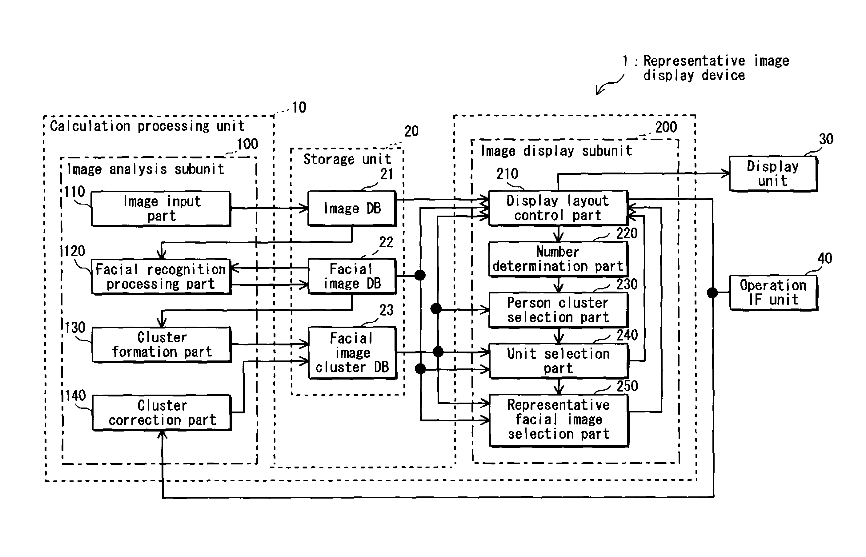
[0059]FIG. 1 shows an overall structure of a representative image display device 1 pertaining to the present embodiment. The representative image display device 1 is composed of a calculation processing unit 10, a storage unit 20, a display unit 30 and an operation interface unit (hereinafter, “operation IF unit”) 40.

[0060]The calculation processing unit 10 is constituted from a central processing unit (CPU) and the like, and performs various types of controls and calculations for the entirety of the representative image display device 1.

[0061]The storage unit 20 is constituted from a read only memory (ROM), a random access memory (RAM), a hard disk drive (HDD), or the like, and stores therein various types of control programs for controlling the representative image display device 1, various types of application programs, etc. The sto...

second embodiment

[Second Embodiment]

[0179]A description is now given of the second embodiment of the present invention with reference to the accompanying drawings.

[0180]The first embodiment has introduced the following features. Similar facial images are grouped together, and each group of similar facial images is included in a different one of units. Similar units are grouped together, and each group of similar units is included in a different one of person clusters. Representative facial images are selected and displayed based on a result of the above grouping. In contrast, the present embodiment introduces the following features. Similar facial images are grouped together, and each group of similar facial images is included in a different one of person clusters. Representative facial images are selected and displayed based on a result of the above groping. Note, the “person clusters” pertaining to the present embodiment are equivalent to “clusters”.

[0181]Also note, the structural elements of the ...


PUM


Abstract

A person cluster selection part selects one or more person clusters as representative person clusters in order of largest number of facial images included therein. A unit selection part selects, from each representative person cluster, (i) a unit having the highest likelihood as a first representative unit, and (ii) units in order of lowest likelihood as a second representative unit onward. A representative facial image selection part selects, from each representative unit, (i) a facial image having the highest likelihood as a first representative facial image, and (ii) facial images in order of lowest likelihood as a second representative facial image onward.

Description

BACKGROUND of the INVENTIONTECHNICAL FIELD[0001]The present invention relates to technology for grouping images captured by a digital still camera, a digital video camera, etc., and displaying the grouped images.BACKGROUND ART[0002]There are conventional methods of grouping images and displaying the grouped images. One of such conventional methods makes use of people shown in the images and groups similar faces into one cluster with the aid of a facial image recognition technique, so that clusters of images showing the same person are displayed cluster-by-cluster.[0003]For the purpose of improving accuracy of facial image clustering, another one of such conventional methods facilitates grouping of people by providing an operation interface (hereinafter, “operation IF”) that enables a user to correct a clustering result (for example, see Non-Patent Literature 1). According to this method, the result of the facial image clustering can be corrected by the user manually editing (annotat...

Claims


Application Information

Patent Timeline
IPC IPC(8): G06K9/62G06F7/00G06K9/00
CPCG06F17/30247G06F16/583
Inventor ISOGAI, KUNIAKIKAWAMURA, TAKASHI
Owner AT&T MOBILITY II LLC
Learn More