
Multi-stand rolling mill of the longitudinal elongator kind for rod-shaped bodies, comprising four-rolls stands, and method for substituting the stands

a technology of longitudinal elongation and multi-stand rolling mill, which is applied in the direction of metal rolling stands, metal rolling, manufacturing tools, etc., can solve the problems of increased manufacturing cost, difficult to solve series of problems, and complex roll control

Inactive Publication Date: 2014-03-25
DANIELI & C OFF MEC SPA
View PDF12 Cites 2 Cited by
  • Summary
  • Abstract
  • Description
  • Claims
  • Application Information

AI Technical Summary

Benefits of technology

The present invention provides a multi-stand rolling mill for rod-shaped bodies, which comprises four-roll stands and a method for substituting the stands. The rolling mill includes a central body and two platforms for carrying and substituting the stands. A transverse translation device acts on the substitution stands to push them against the corresponding stands on the central body. The method includes prearranging the substitution stands, unlocking the spindles, translating the stands, and locking the spindles to restart the rolling process. The technical effects of the invention are improved efficiency, flexibility, and reduced downtime for maintenance and repair.

Problems solved by technology

The known types have complex roll controls because of the need to insert a high number of motors and corresponding accessories.
On the other hand, a four-roll-stand rolling mill implies a series of problems which are difficult to be solved.
The number of auxiliary components needed and thus the manufacturing cost are increased.
Furthermore, several necessary operations are more difficult, such as the operations for substituting the stands while rolling, which requires a long time and a series of manual operations, and for rotating the rolls to prevent the misalignment between successive rolls, which would risk causing scoring phenomena on the rod-shaped body.
A further problem consists in that a four-roll-stand rolling mill has the difficulty of offsetting the two successive stands by 45°, such a condition makes it difficult to practically implement the structure of the rolling mill and roll / stand change.
This type of stands may not be used universally because the idle rolls do not exert any pulling action.

Method used


Image

  • Multi-stand rolling mill of the longitudinal elongator kind for rod-shaped bodies, comprising four-rolls stands, and method for substituting the stands
  • Multi-stand rolling mill of the longitudinal elongator kind for rod-shaped bodies, comprising four-rolls stands, and method for substituting the stands
  • Multi-stand rolling mill of the longitudinal elongator kind for rod-shaped bodies, comprising four-rolls stands, and method for substituting the stands

Examples


Embodiment Construction

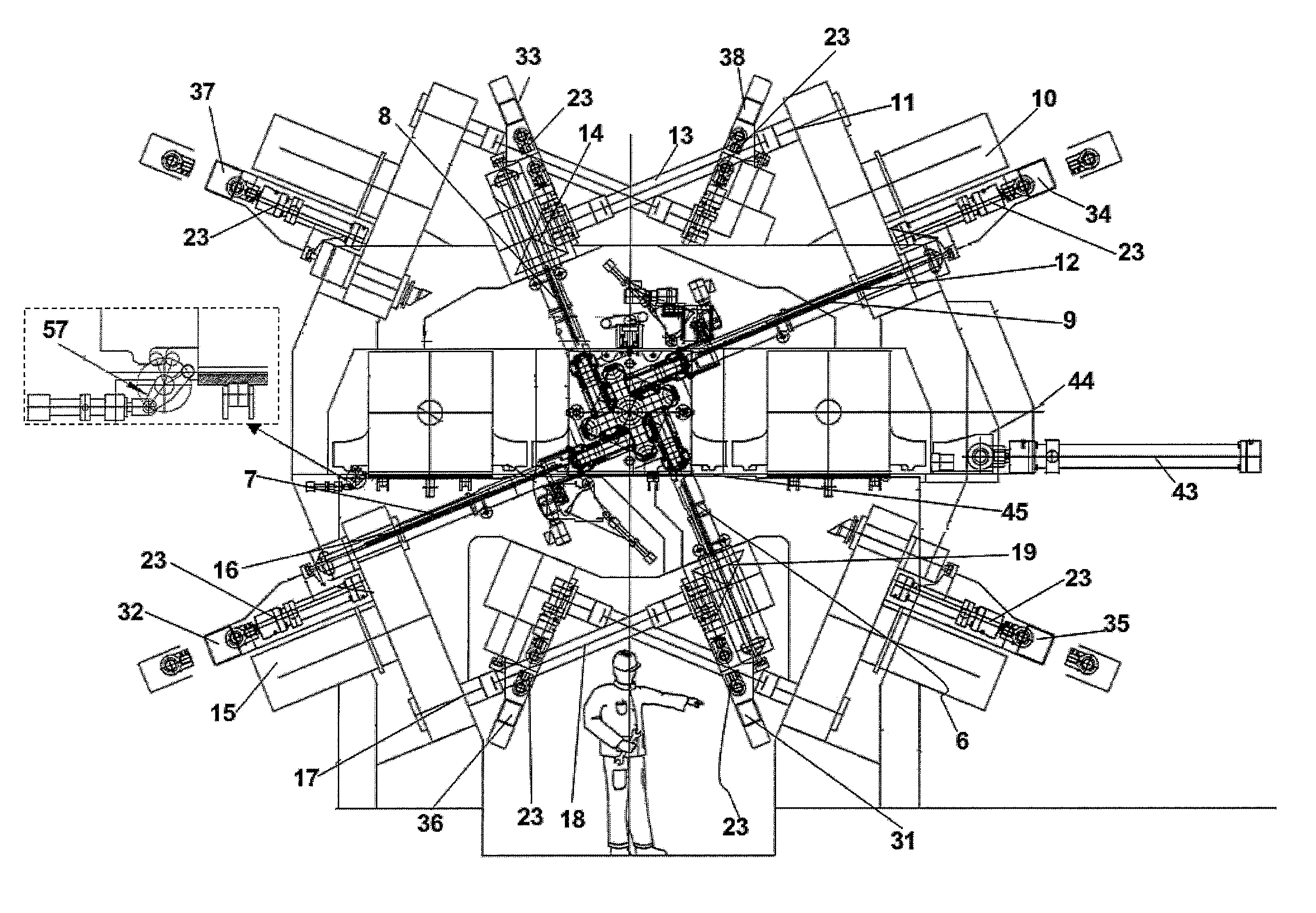
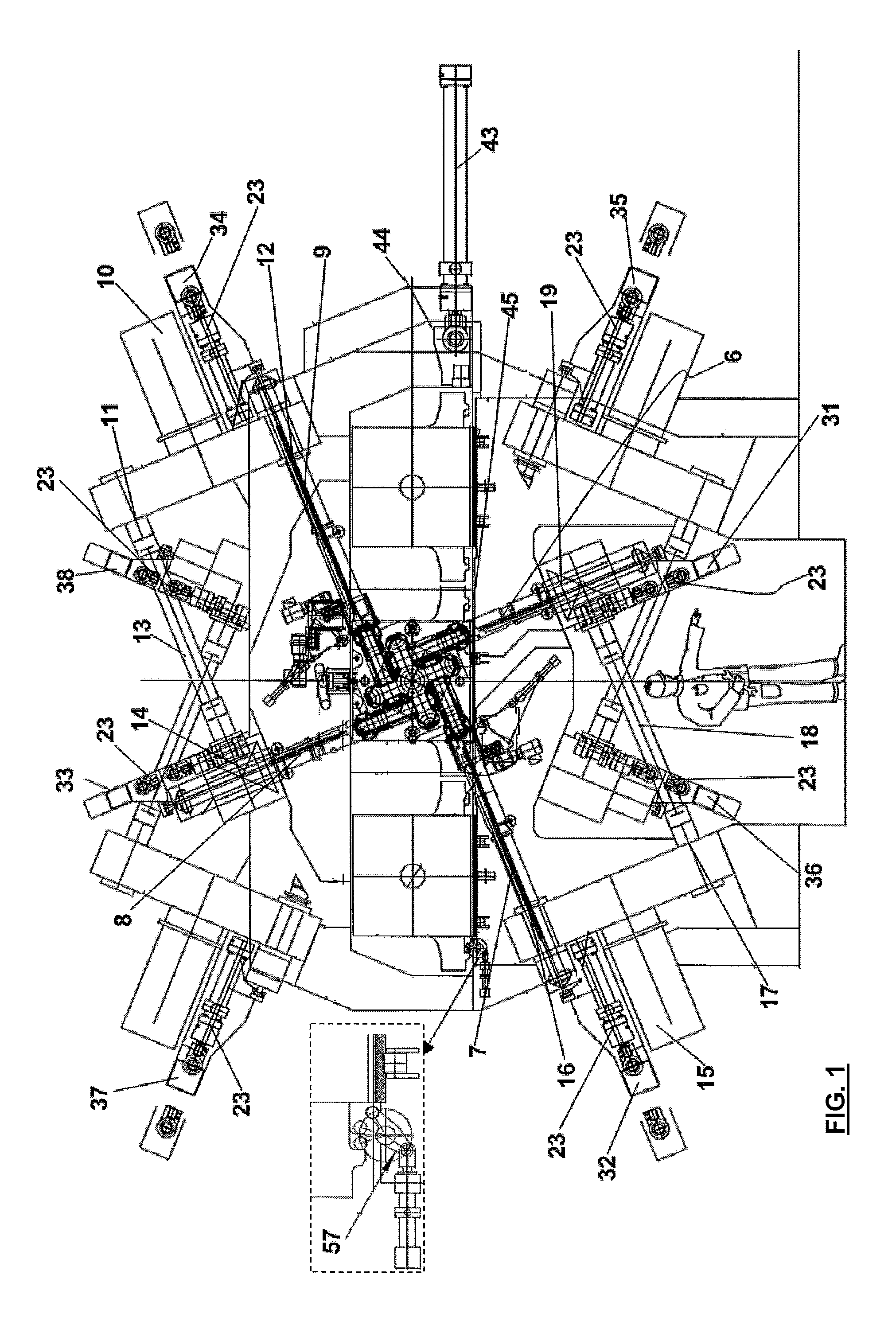
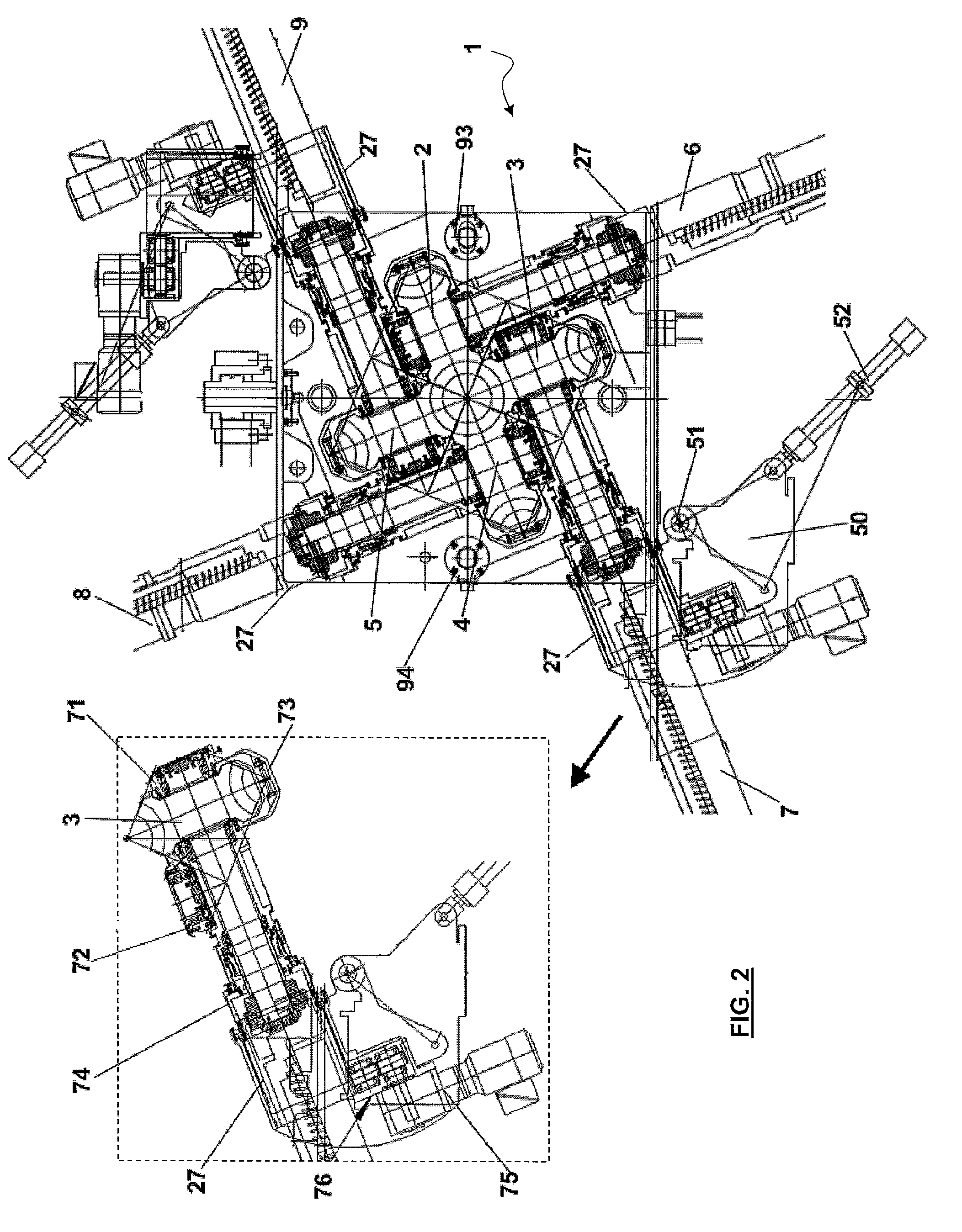
[0033]With particular reference to FIGS. 1, 2 and 3, a stand 1 in accordance with an aspect of the present invention comprises four rolls 2, 3, 4 and 5, each of which is provided with a corresponding control spindle, 6, 7, 8, and 9, respectively.

[0034]All rolls are motorized, but two neighbouring rolls are controlled by means of a single motor with appropriate motion transmission linkages.

[0035]The total number of the motors is thus double the number of the stands. In particular, rolls 4 and 5 are controlled by means of the motor 10, which is connected to a splitter reducer with two outputs 11, 12: output 12 directly controls the spindle 9, while output 11 controls the spindle 8 by means of the spindle 13 and the 90° transmission 14.

[0036]Similarly, rolls 2 and 3 are controlled by means of the motor 15, which is connected to a splitter reducer with two outputs 16, 17: the output 16 directly controls the spindle 7, while the output 17 controls the spindle 6 by means of the spindle 18...


PUM

PropertyMeasurementUnit
lengthaaaaaaaaaa
anglesaaaaaaaaaa
rotationaaaaaaaaaa

Abstract

There is described multi-stand rolling mill with stands having four motorized rolls and provided with controls outside the stand and retractile spindles, which comprises a central body with said stands; a first platform (41) on a side charge position carrying the substitution stands; a second platform (42) on a side discharge position, opposite to said side charge position; a transversal translation device (43, 44) adapted to push the substitution stands against the corresponding stands to be substituted on the central body. The stands to be substituted translate on the second platform, and the substitution stands substitute the stands to be substituted in the central body.

Description

FIELD OF THE INVENTION[0001]The present invention relates to a multi-stand rolling mill of the longitudinal elongator kind for rod-shaped bodies, comprising stands having four motorized rolls, and a method for substituting the stands.STATE OF THE ART[0002]It is known that the longitudinal rolling of rod-shaped bodies, in particular of tubes or rods, is carried out by means of multi-stand rolling mills having motorized rolls, in which each stand is provided with two or three rolls, and the position of said rolls may be advantageously adjusted by changing the distance of the roll itself from the rolling axis, in order to change the rolling conditions and the reductions at each stand.[0003]On the other hand, machines of this type may have a high number of stands (higher than 15-16, up to 32 stands), of considerable length (e.g. 10-12 m), with a small minimum distance between axes in order to minimize the head and tail parts of rod-shaped bodies, which should be rejected, because they a...

Claims


Application Information

Patent Timeline
Patent Type & Authority Patents(United States)
IPC IPC(8): B21B13/12
CPCB21B13/103B21B31/10B21B2203/06B21B2013/025B21B13/005B21B35/04B21B1/18
Inventor CERNUSCHI, ETTOREBERTELLI, ARISTIDE GIACOMOKULESSA, GERHARD
Owner DANIELI & C OFF MEC SPA
Learn More