
Fluid control system for steerable agricultural implement

a technology of control system and steerable agricultural implement, which is applied in the direction of process control, instruments, application, etc., can solve the problem that the large turning radius may complicate the process of maneuvering the implement through turns

Active Publication Date: 2014-02-04
BLUE LEAF I P INC
View PDF31 Cites 9 Cited by
  • Summary
  • Abstract
  • Description
  • Claims
  • Application Information

AI Technical Summary

Benefits of technology

The present invention is for a steerable agricultural implement that has a fluid control system to automatically identify fluid supply and return conduits. It includes a valve to control fluid flow to the wheels and a controller to automatically centering and steering the wheels. The technical effect is to make the implementation easier to use and more efficient in its operation.

Problems solved by technology

The larger turning radius may complicate the process of maneuvering the implement through turns, such as when turning off a narrow road and / or through a narrow pass into a field, or when maneuvering through other tight spots.

Method used


Image

  • Fluid control system for steerable agricultural implement
  • Fluid control system for steerable agricultural implement
  • Fluid control system for steerable agricultural implement

Examples


Embodiment Construction

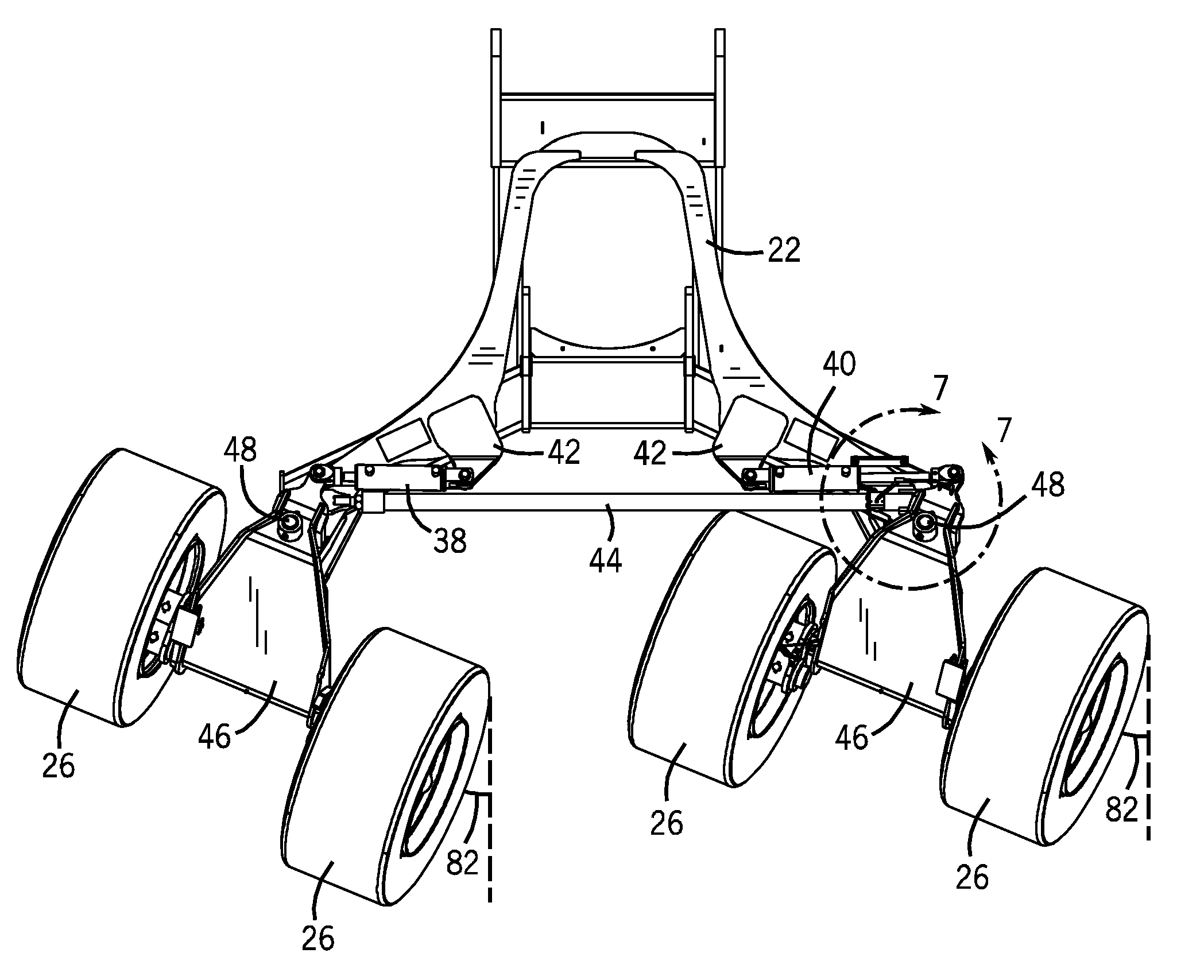
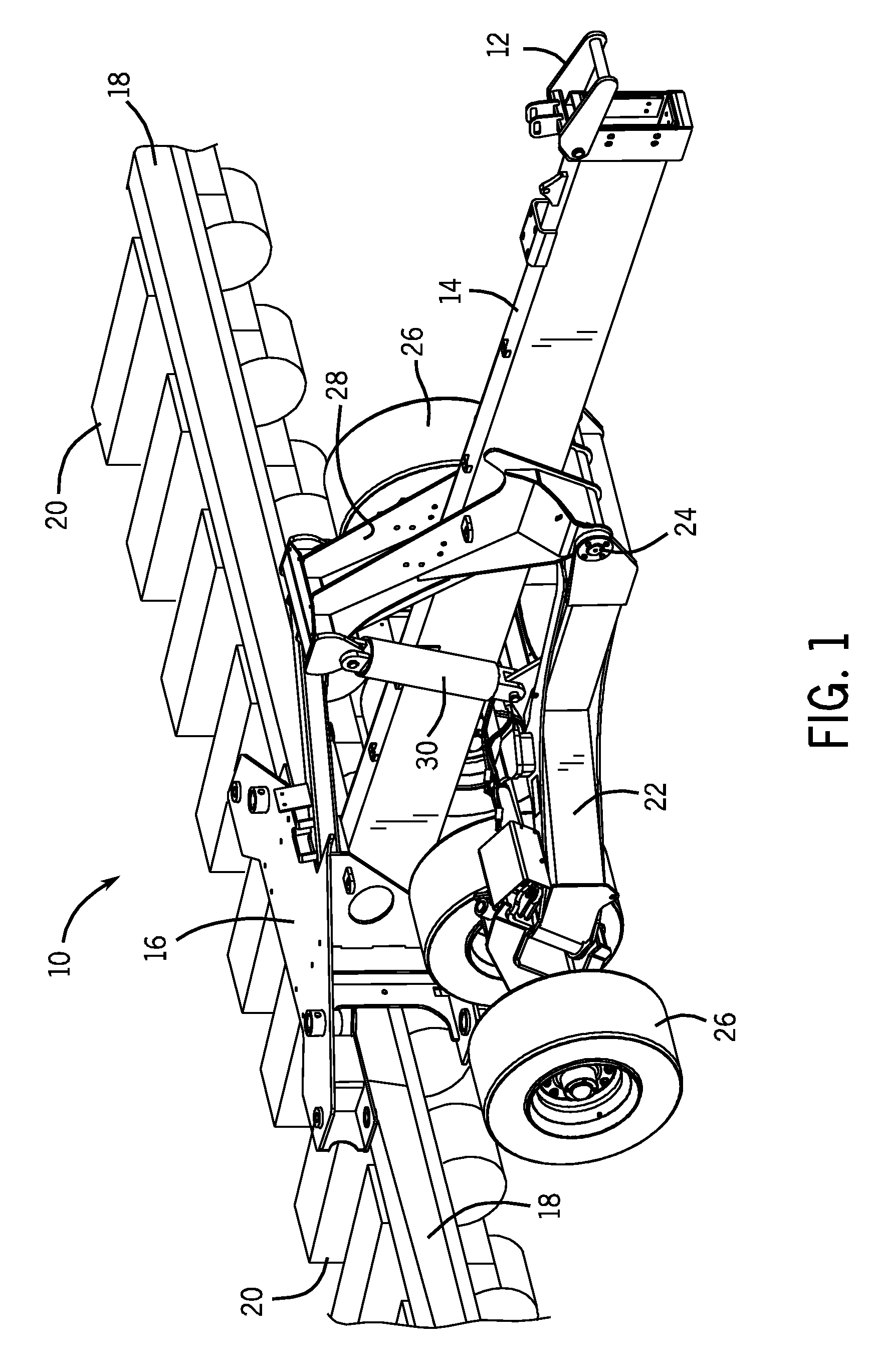
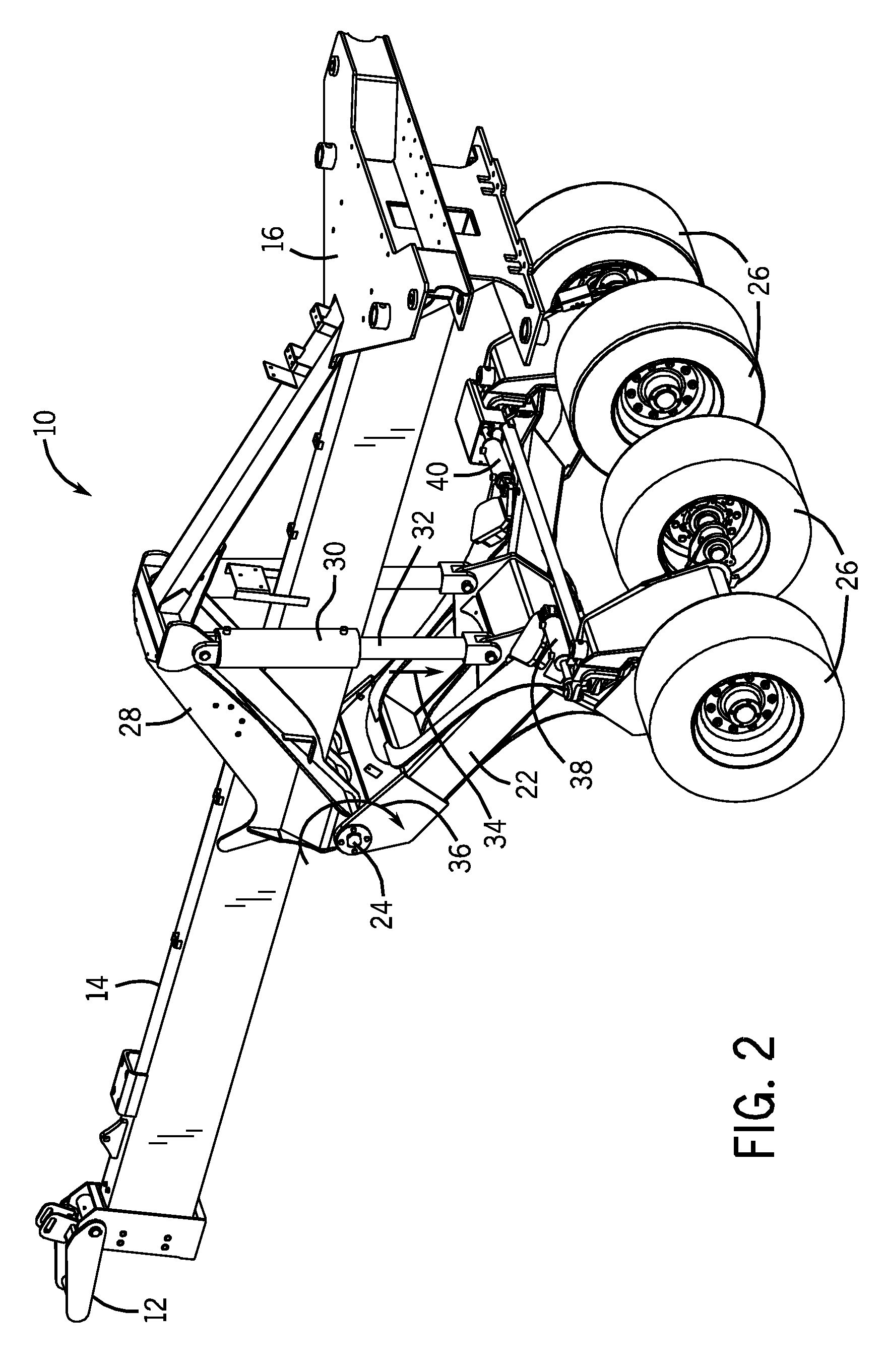
[0016]Turning now to the drawings, FIG. 1 is a perspective view of an agricultural implement 10 in a working position. The implement 10 is designed to be towed behind a prime mover such as a tractor. The implement includes a tow hitch 12 which is coupled to a hitch assembly 14. The tow hitch 12 may be used to attach the implement 10 to a tractor and may be pivotally coupled to the hitch assembly 14 to facilitate flexibility as the implement changes elevation as it is towed across a field. A toolbar mounting structure 16 is coupled to the hitch assembly 14, and configured to pivotally secure toolbars 18. In the illustrated working position, the toolbars extend laterally outward from the mounting structure 16. Multiple row units 20, configured to deposit seeds and / or fertilizer into soil, are coupled to the toolbars 18. In the present embodiment, the toolbars 18 are configured to fold forward when the implement 10 is in a transport position. When in the transport position, the toolbar...


PUM


Abstract

An agricultural implement system is provided that includes a valve in fluid communication with first and second actuating cylinders and with first and second fluid conduits. The valve is configured to control fluid flow from the first and second fluid conduits to the first and second actuating cylinders. Furthermore, a controller is communicatively coupled to first and second pressure sensors and to the valve. The first pressure sensor is coupled to the first fluid conduit, and the second pressure sensor is coupled to the second fluid conduit. The controller is configured to determine whether the first fluid conduit or the second fluid conduit is supplying fluid to the valve based on signals from the first and second pressure sensors, and to automatically control fluid flow to the first and second actuating cylinders such that wheel assemblies are rotated to a desired angle relative to an implement frame.

Description

BACKGROUND[0001]The invention relates generally to ground working equipment, such as agricultural equipment, and more specifically, to a fluid control system for a steerable agricultural implement.[0002]A wide range of farm implements have been developed and are presently in use for tilling, planting, harvesting, and so forth. Seeders or planters, for example, are commonly towed behind tractors and may cover wide swaths of ground which may be tilled or untilled. Such devices typically open the soil, dispense seeds in the opening, and close the soil in a single operation. Seeds are commonly dispensed from seed tanks and distributed to row units by a distribution system. To make the seeding operation as efficient as possible, very wide swaths may be covered by extending wings on either side of a central section of the implement pulled by the tractor. Included in the wing assemblies are tool bars, row units mounted thereon, and support wheels. The wings and row units are commonly dispo...

Claims


Application Information

Patent Timeline
Patent Type & Authority Patents(United States)
IPC IPC(8): A01B69/00
CPCF15B2211/3144F15B2211/327F15B2211/7121A01B63/22F15B2211/3051Y10T137/7762Y10T137/1044Y10T137/86582Y10T137/7837
Inventor DIAZ, RICARDOBETTIN, LEONARD A.
Owner BLUE LEAF I P INC
Learn More