
Scooter device mounting assembly

Active Publication Date: 2013-12-24
HIGH GEAR SPECIALTIES
View PDF24 Cites 30 Cited by
  • Summary
  • Abstract
  • Description
  • Claims
  • Application Information

AI Technical Summary

Benefits of technology

The solution effectively secures portable devices to scooters, preventing them from becoming projectiles during accidents and maintaining stability despite vibrations and jarring, thereby enhancing rider and public safety.

Problems solved by technology

These pin connections help resist relative movement at such locations under normal operating conditions of the vehicle, but may be severed in response to the application of a sufficient force to the assembly, such as during an accident, to resist disengagement of the portable device from the vehicle.

Method used


Image

  • Scooter device mounting assembly
  • Scooter device mounting assembly
  • Scooter device mounting assembly

Examples


Embodiment Construction

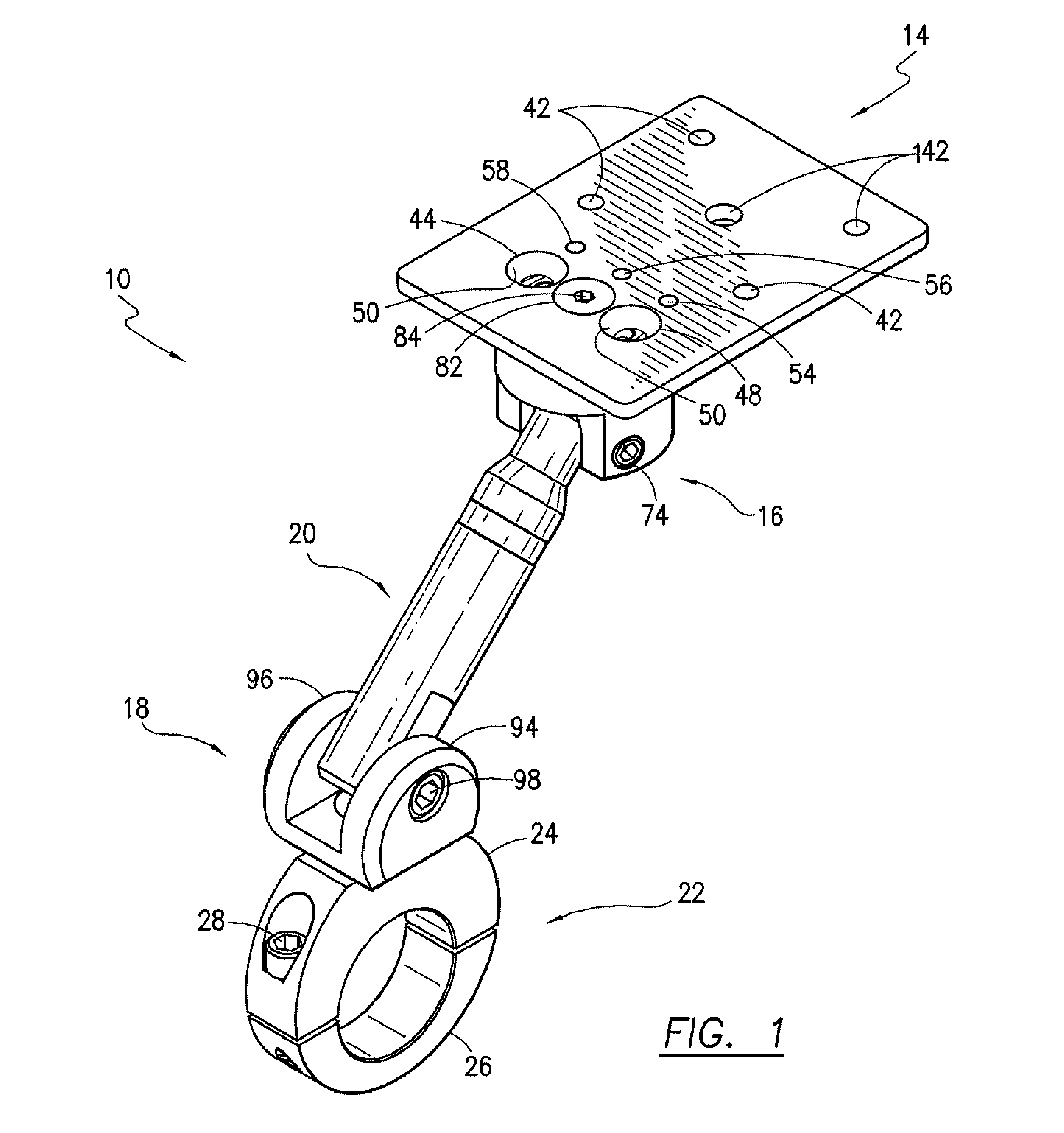
[0039]Referring initially to FIGS. 1, 8 and 9, two types of vehicle mounts according to this invention are shown. As discussed above, mounts for supporting portable items such as radar detectors, toll road transponders, GPS devices, cellular telephones, cameras, change holders, garage door openers, PDAs, radios and other devices have been designed for attachment to different locations on motorcycles and other vehicles. For purposes of illustration, a handlebar mount 10 is depicted in FIG. 1 and a stem mount 12 is shown in FIG. 9. It should be understood that the following discussion applies to any type of vehicle mount for motorcycles and other vehicles, and is not intended to be limited to the mounts 10 and 12.

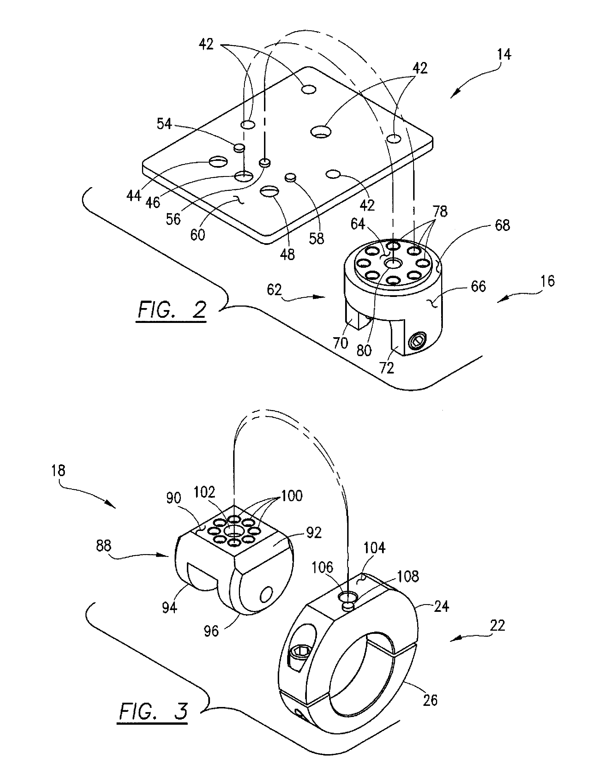
[0040]Each of the mounts 10 and 12 comprises a device mounting plate 14, an upper coupler 16, a lower coupler 18, a shaft 20 connected between the upper and lower couplers 16, 18, and, a vehicle mounting element 22. The term “vehicle mounting element” as used herein is meant ...


PUM


Abstract

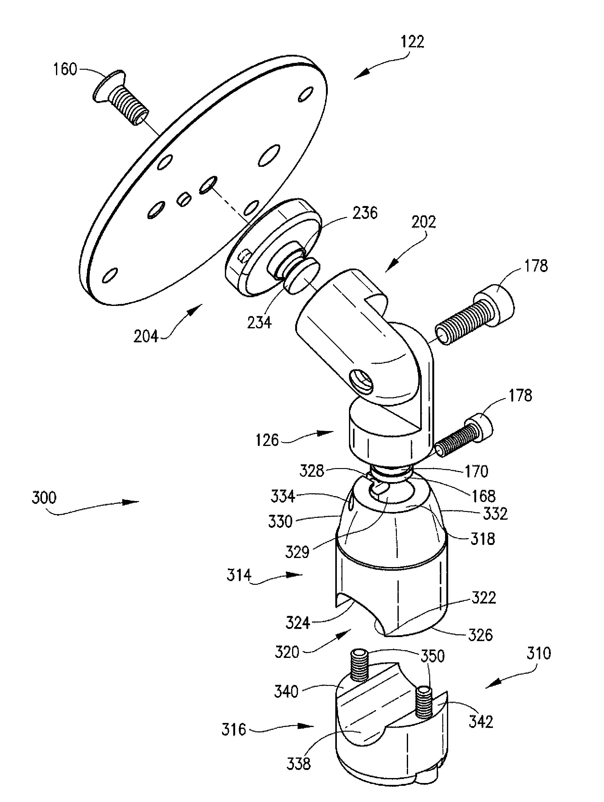
A device mounting assembly particularly intended for connection to the mirror mount of a motorized scooter so that a portable device such as a cellular telephone may be positioned for ready access by the rider of the scooter includes a severable pin connection at the location where the assembly is coupled to the vehicle and / or to a portable device wherein the pin connections help resist relative movement at such locations under normal operating conditions of the vehicle but may be severed in response to the application of a sufficient force to the assembly to resist disengagement of the portable device from the vehicle.

Description

CROSS REFERENCE TO RELATED APPLICATIONS[0001]This application is a continuation-in-part of and claims priority under 35 U.S.C. §120 to co-pending U.S. application Ser. No. 13 / 351,260 filed Jan. 17, 2012 which is a continuation-in-part of U.S. application Ser. No. 12 / 711,767 filed Feb. 24, 2010, now U.S. Pat. No. 8,261,954 issued Sep. 11, 2012. U.S. application Ser. Nos. 12 / 711,767 and 13 / 351,260 are expressly incorporated herein by reference in their entirety to form a part of the present disclosure.FIELD OF THE INVENTION[0002]This invention relates to mounts for securing portable devices to vehicles, and, more particularly, to a device mounting assembly for a scooter that resists relative rotational movement at the connection between the assembly and the scooter and at the connection between the assembly and the portable device while permitting disengagement at one or both of such connections in response to the application of a sufficient force to the mount.BACKGROUND OF THE INVENT...

Claims


Application Information

Patent Timeline
Patent Type & Authority Patents(United States)
IPC IPC(8): B60R7/04
CPCB62J11/00F16M11/08F16M11/2014F16M11/2021F16M13/022F16M11/041B60R11/02B60R2011/0059B60R2011/0066B60R2011/008F16M2200/024B62J2099/0033B62J50/225
Inventor LEE, MICHAEL F.
Owner HIGH GEAR SPECIALTIES
Learn More