
Switch module, electronic device using the same and method for manufacturing the same

a technology of electronic devices and switches, applied in the direction of pulse techniques, instruments, optical radiation measurement, etc., can solve the problems of difficult integration and inability to integrate elements

Active Publication Date: 2013-11-19
INNOLUX CORP +1
View PDF3 Cites 0 Cited by
  • Summary
  • Abstract
  • Description
  • Claims
  • Application Information

AI Technical Summary

Benefits of technology

Enables the integration of multiple functions within a single module, allowing for infrared light reception, button functionality, and visible light indication, while maintaining the desired design attributes of lightweight, slimness, and aesthetics in electronic devices.

Problems solved by technology

However, such integration is not easy because different elements have different attributes.
After a long period of tests and trials, some designers have developed such a thought that some elements cannot be integrated.

Method used


Image

  • Switch module, electronic device using the same and method for manufacturing the same
  • Switch module, electronic device using the same and method for manufacturing the same
  • Switch module, electronic device using the same and method for manufacturing the same

Examples


Embodiment Construction

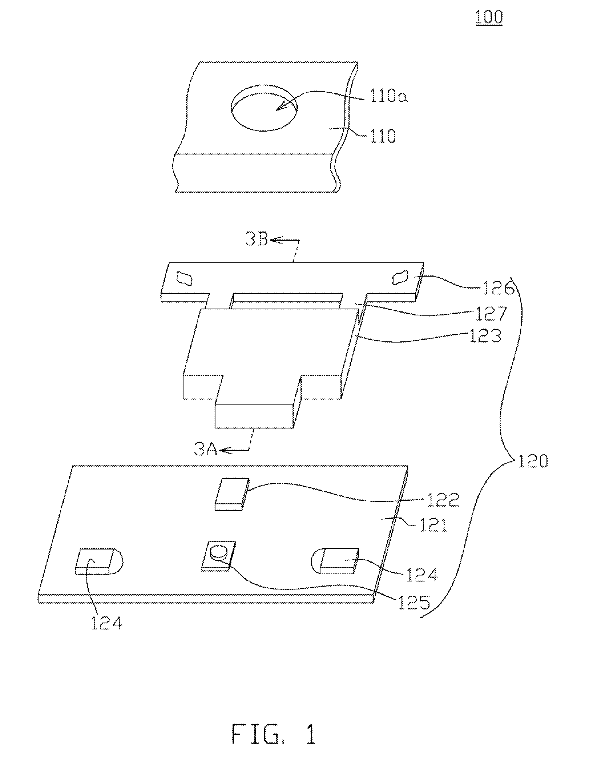
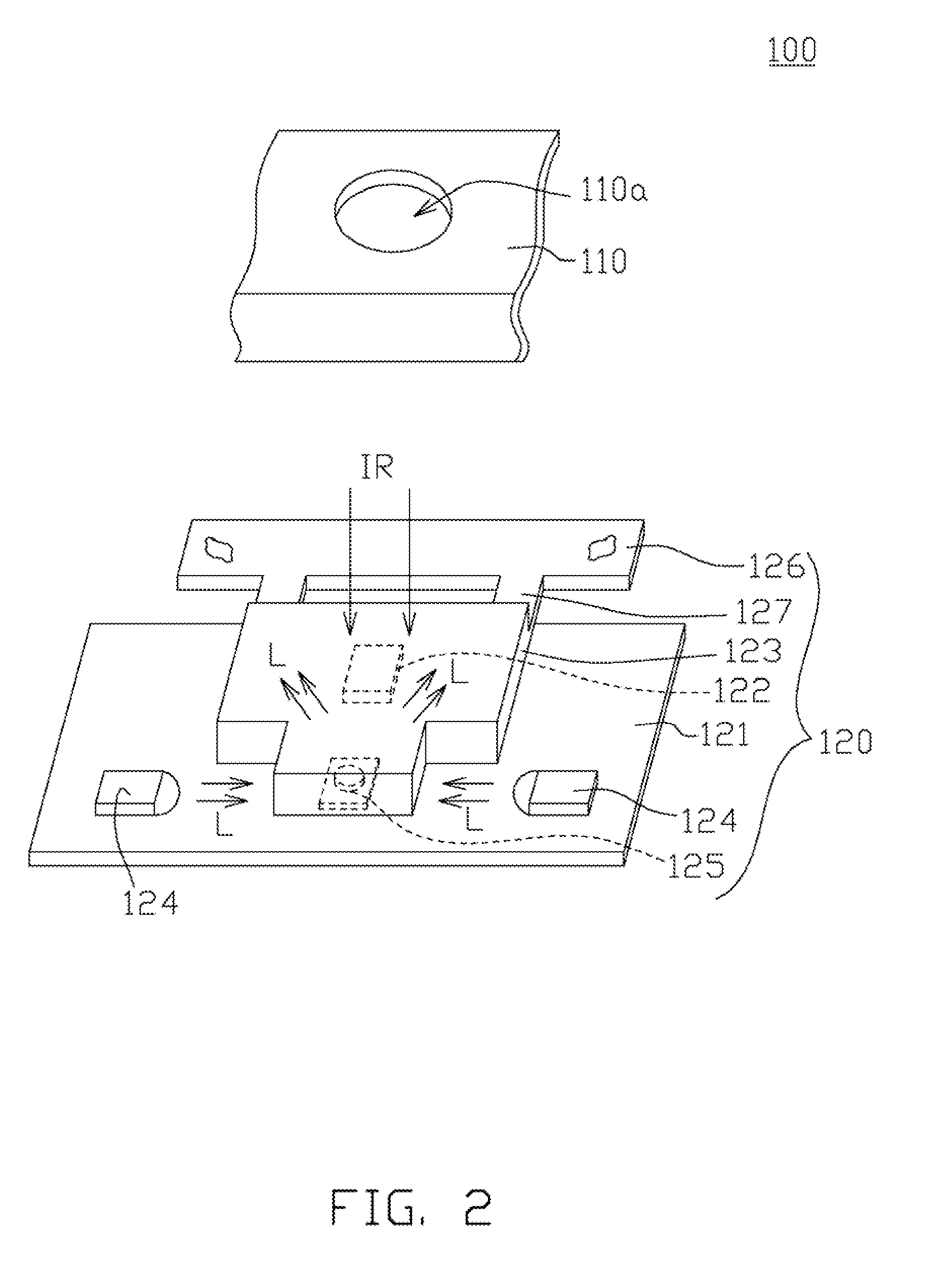
[0019]Referring to both FIG. 1 and FIG. 2. FIG. 1 shows a decomposition diagram of an electronic device 100 according to a first embodiment of the disclosure. FIG. 2 shows an assembly diagram of a portion of the elements of FIG. 1. The electronic device 100 includes an outer casing 110 and a switch module 120. In the present embodiment of the disclosure, the electronic device 100 is realized by such as a computer, a display screen or a TV. The switch module 120 is disposed inside the outer casing 110. The outer casing 110 has an opening 110a, which exposes a portion of the switch module 120. The switch module 120 includes a circuit board 121, an IR light receiver 122, a cover 123, at least one light emitting unit 124 and a button 125. As indicated in FIG. 2, the IR light receiver 122, the light emitting unit 124 and the button 125 are all disposed on the circuit board 121. The cover 123 covers the IR light receiver 122 and the button 125.

[0020]As indicated in FIG. 2, the IR light re...


PUM

PropertyMeasurementUnit
transparencyaaaaaaaaaa
flexibleaaaaaaaaaa
photo transmissionaaaaaaaaaa

Abstract

A switch module, an electronic device using the same and a method for manufacturing the same are provided. The switch module includes a circuit board, an infrared (IR) light receiver, at least one light emitting unit and a cover. The IR light receiver is disposed on the circuit board for receiving an infrared light. The light emitting unit is disposed on the circuit board for emitting a visible light. The cover includes a first casing and a second casing, and covers the IR light receiver. The first casing shields the IR light receiver. The second casing is connected to the second casing. The transparency of the second casing is larger than that of the first casing. The second casing receives the visible light and then the visible light is emitted to the outside of the second casing.

Description

[0001]This application claims the benefit of China application Serial No. 2010102755200.X, filed Sep. 8, 2010, the subject matter of which is incorporated herein by reference.BACKGROUND[0002]1. Technical Field[0003]The disclosure relates in general to a switch module, an electronic device using the same and a method for manufacturing the same, and more particularly to a switch module, an electronic device using the same and a method for manufacturing the same with both infrared light reception function and indicator function.[0004]2. Description of Related Art[0005]With the advance in technology, various electronic devices are constantly provided. In order to achieve some particular functions, many electronic devices have the design of disposing some of the elements on the outer casing.[0006]In the pursuit of the trend of lightweight, slimness, compactness and aesthetics, the designers are dedicated to integrating the elements which are disposed on the outer casing of an electronic ...

Claims


Application Information

Patent Timeline
Patent Type & Authority Patents(United States)
IPC IPC(8): G01J5/00
CPCH03J9/06H03K17/941H03K2017/9455H03K2217/94106Y10T29/49105
Inventor FU, ZE-SENTSENG, REN-WEI
Owner INNOLUX CORP
Learn More