
Worm drive adjustment for headgear suspension

a headgear and worm drive technology, applied in the direction of headwear caps, hats, protective garments, etc., can solve the problems of disadvantages of ratchet mechanism size and weight, and achieve the effects of large gear reduction, convenient operation, and considerable mechanical advantag

Active Publication Date: 2013-11-12
GENTEX CORP
View PDF17 Cites 8 Cited by
  • Summary
  • Abstract
  • Description
  • Claims
  • Application Information

AI Technical Summary

Benefits of technology

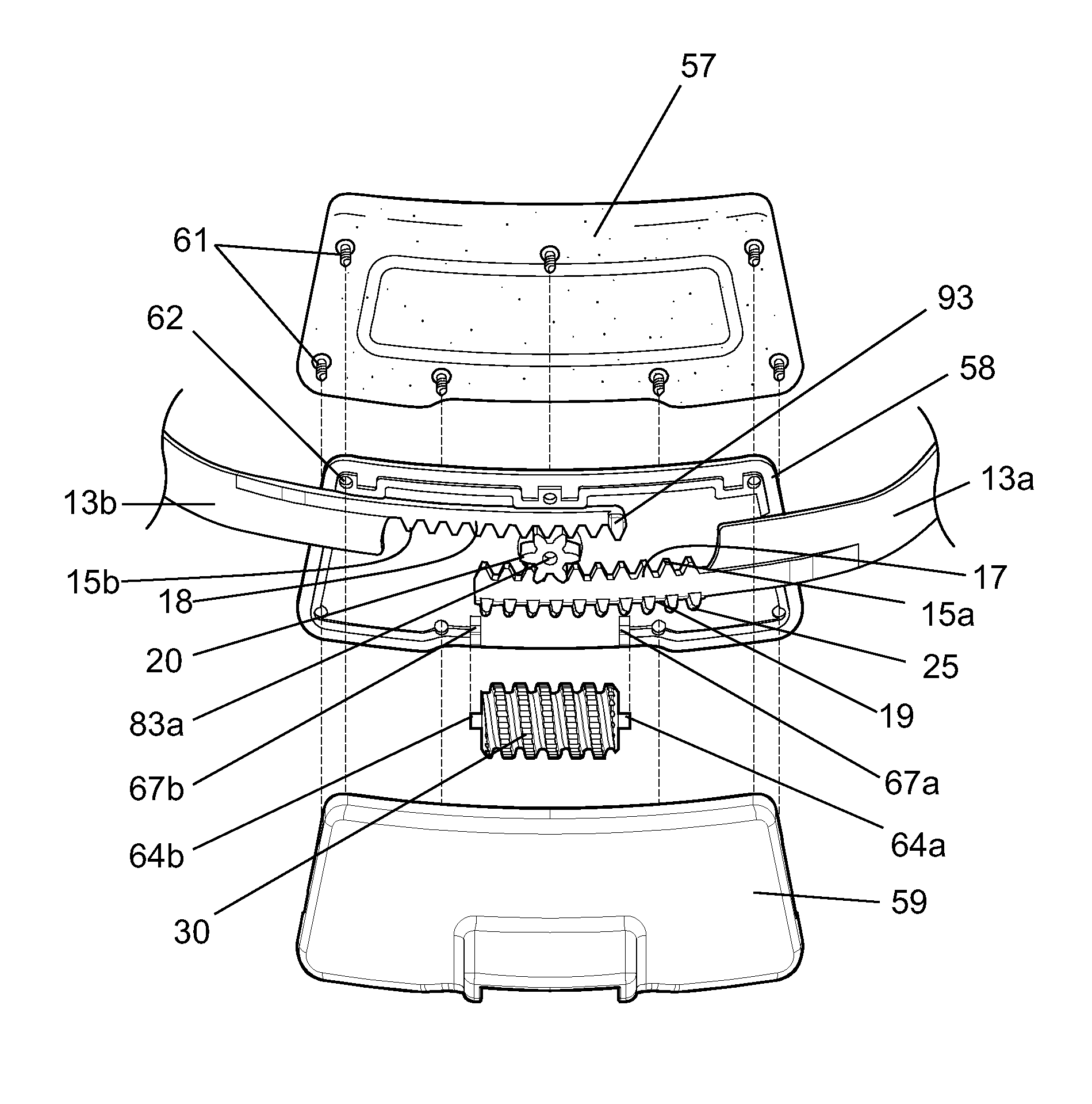
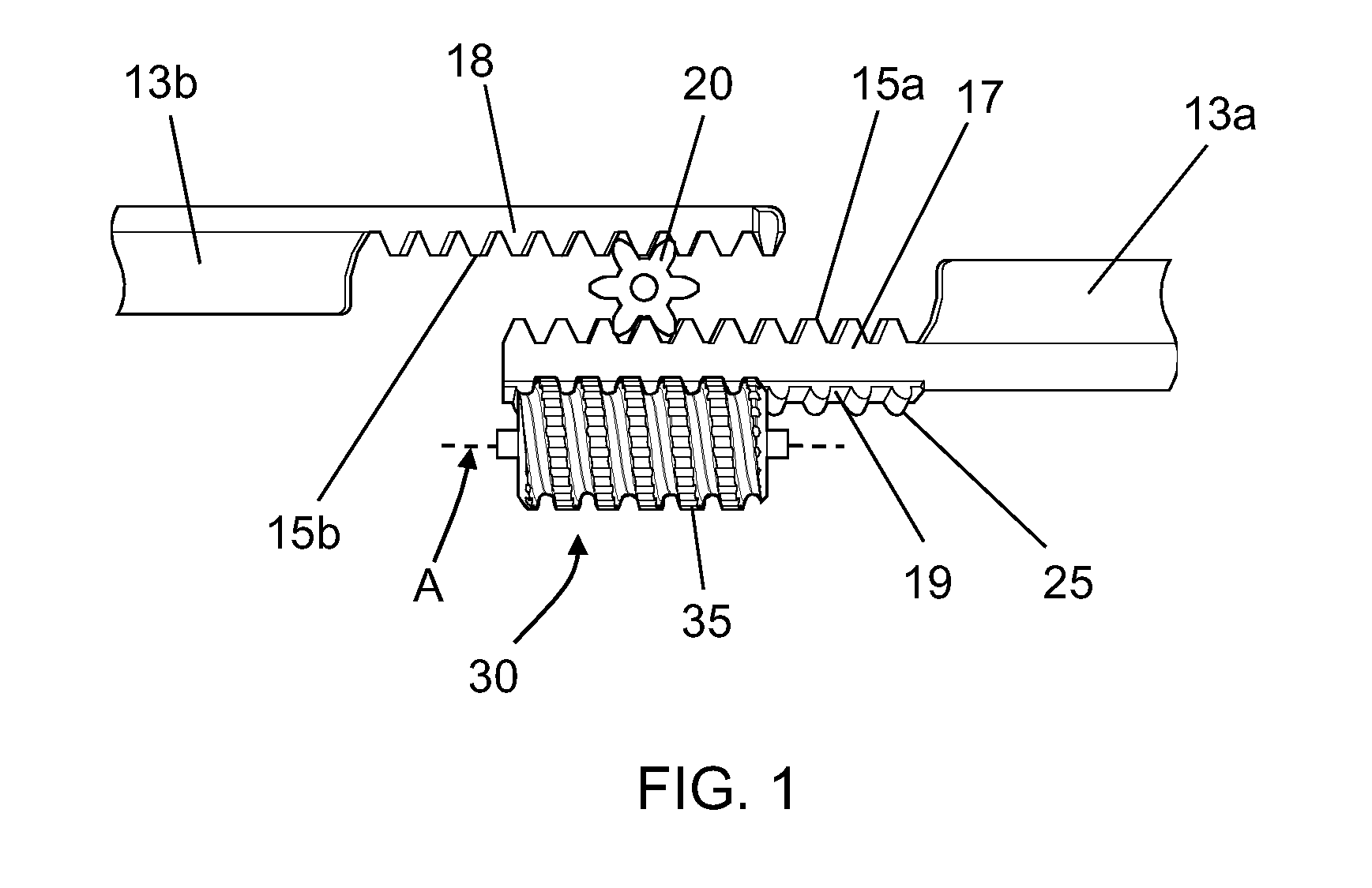
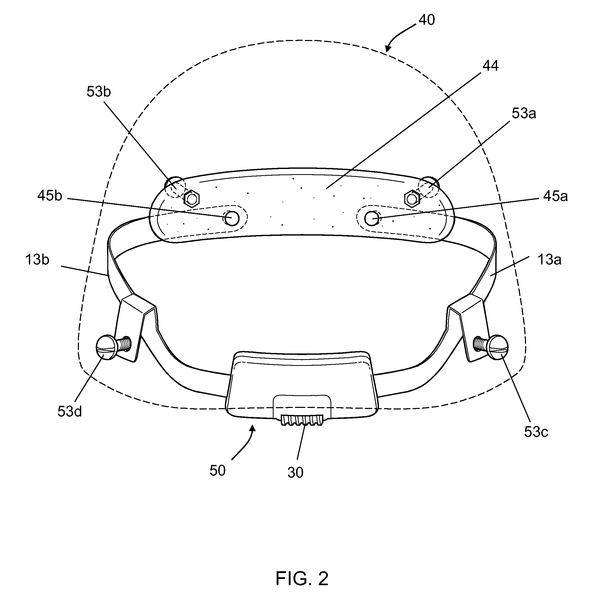
[0010]The present invention provides a small, low-profile, continuous adjustment mechanism for a headgear suspension. The adjustment mechanism includes a worm drive, which provides a large gear reduction and considerable mechanical advantage, thereby making the adjustment mechanism easy to operate (e.g., it may be operated by one finger of a wearer). The large gear reduction also provides self braking to retain the headgear in its adjusted position. During operation of the worm drive, the adjustment mechanism advantageously remains in a fixed location along a perimeter of the headgear, thereby facilitating access by the wearer. In addition, due to its small size and low profile, the adjustment mechanism may be fit into small spaces in a wide variety of headgear devices, such as, for example, a helmet where the adjustment mechanism may be located just below a rim of the external shell. The adjustment mechanism also provides a continuous, non-ratcheted adjustment, which allows the fit of the headgear to be fine-tuned over a range of interest. The adjustment mechanism and headgear suspension may be made of resilient plastic materials.
[0013]In certain embodiments, the worm rack and the first pinion rack are disposed along opposite sides of the first headband element. In another embodiment, the worm rack includes teeth having a worm cut, and the first and second pinion racks include teeth having a spur gear cut. The headgear adjustment mechanism may include a forehead pad affixed to at least one of the first and second headband elements. The forehead pad may be configured to be disposed on a wearer's forehead. In certain embodiments, an external surface of the worm includes a knurled, ribbed, or roughened surface to facilitate engagement with a wearer's finger.
[0014]In certain embodiments, the first and second headband elements, the spur gear, and the worm, are made of plastic. The plastic may include resilient plastic, nylon, polypropylene, polystyrene, polyvinyl chloride, polyester, acrylonitrile butadiene styrene, and / or polyethylene. Rotation of the worm may allow non-ratcheted, continuous adjustment of the first and second headband elements.
[0015]In certain embodiments, the housing aligns the worm with the worm rack and the spur gear with the first and second pinion racks. The housing may include a stop to prevent movement of the first and second headband elements beyond a predetermined position. The stop may include an abutment disposed within a track. The abutment may be attached to the housing and the track may include a slot disposed longitudinally along at least one of the first and second headband elements. In certain embodiments, the abutment and track are configured to guide movement of at least one of the first and second headband elements during rotation of the worm. In another embodiment, rotation of the worm in a first rotational direction causes the first and second headband elements to move closer together, and rotation of the worm in a second rotational direction causes the first and second headband elements to move further apart.

Problems solved by technology

The size and weight of the ratchet mechanism and the knob have disadvantages in some applications.

Method used


Image

  • Worm drive adjustment for headgear suspension
  • Worm drive adjustment for headgear suspension
  • Worm drive adjustment for headgear suspension

Examples


Embodiment Construction

[0029]It is contemplated that devices, systems, methods, and processes of the claimed invention encompass variations and adaptations developed using information from the embodiments described herein. Adaptation and / or modification of the devices, systems, methods, and processes described herein may be performed by those of ordinary skill in the relevant art.

[0030]Throughout the description, where devices and systems are described as having, including, or comprising specific components, or where processes and methods are described as having, including, or comprising specific steps, it is contemplated that, additionally, there are devices and systems of the present invention that consist essentially of, or consist of, the recited components, and that there are processes and methods according to the present invention that consist essentially of, or consist of, the recited processing steps.

[0031]It should be understood that the order of steps or order for performing certain actions is i...


PUM


Abstract

A headgear adjustment mechanism is provided that includes a worm having a central axis of rotation, a first headband element, a second headband element, a spur gear, and a housing. The first headband element includes (i) a worm rack disposed in operative engagement with the worm, and (ii) a first pinion rack. The second headband element includes a second pinion rack. The spur gear is disposed in simultaneous operative engagement with the first pinion rack and the second pinion rack, and the housing at least partially encloses the first and second headband elements. During operation of the adjustment mechanism, rotation of the worm about the axis of rotation causes the first headband element and the second headband element to translate in opposite directions with respect to the worm, thereby adjusting a fit of the headgear.

Description

RELATED APPLICATION[0001]This application claims priority to and the benefit of, and incorporates herein by reference in its entirety, U.S. Provisional Patent Application No. 61 / 339,435, which was filed on Mar. 4, 2010.FIELD OF THE INVENTION[0002]This invention relates to headgear suspensions and specifically to a gear mechanism used to adjust the fit of a headgear suspension system.BACKGROUND OF THE INVENTION[0003]Headgear suspensions are worn in a variety of environments and for various purposes. Headgear suspensions allow protective equipment, such as face shields and helmets, to be suspended from the head. A common element of headgear suspensions is the headband, usually fabricated from a thin band of plastic material formed into a generally circular shape with ends overlapping and joined at the back of the head.[0004]Various means have been devised to adjust the girth of the headband to the extent necessary to fit the variety of head shapes and sizes of different wearers. One s...

Claims


Application Information

Patent Timeline
Patent Type & Authority Patents(United States)
IPC IPC(8): A42B1/22
CPCA42B3/145A42B3/08
Inventor ROGERS, DAVID C.NOORDZIJ, DUCO W.STOKES, PETER L.KOENIG, LEONARD M.
Owner GENTEX CORP
Learn More