Flow reversing device and fluid treatment apparatus
a flow reversing and fluid treatment technology, applied in the direction of suction devices, thin material handling, other medical devices, etc., can solve the problems that all the devices briefly mentioned above were susceptible to improvement, and achieve the effect of convenient and rapid actuation
- Summary
- Abstract
- Description
- Claims
- Application Information
AI Technical Summary
Benefits of technology
Problems solved by technology
Method used
Image
Examples
second embodiment
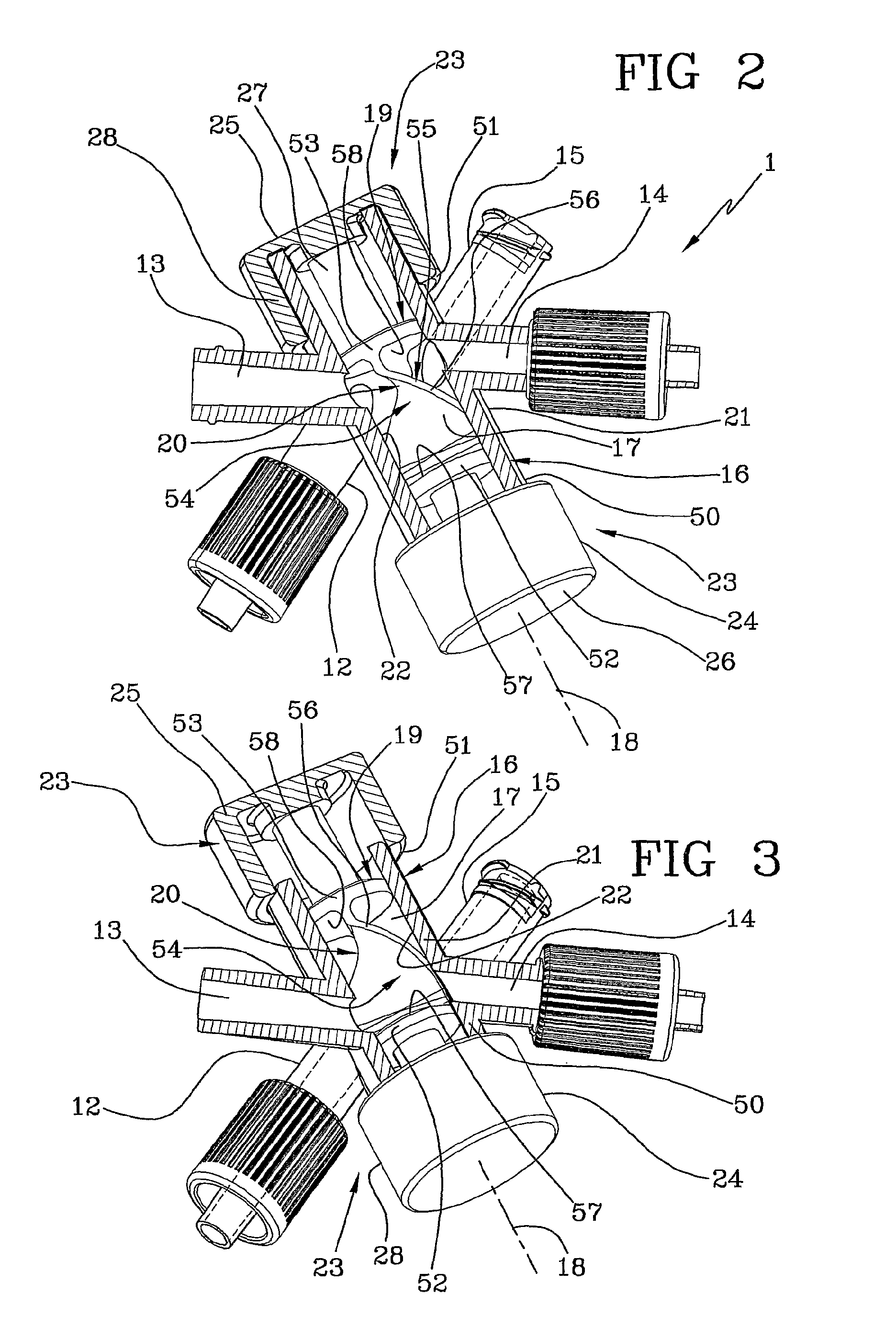
[0061]Notice that while the device 1 shown in FIGS. 9-10 is the second embodiment device of FIGS. 2 and 3 any device according to the present invention can be inserted the same way in the blood circuit 3 of FIGS. 9, 10.
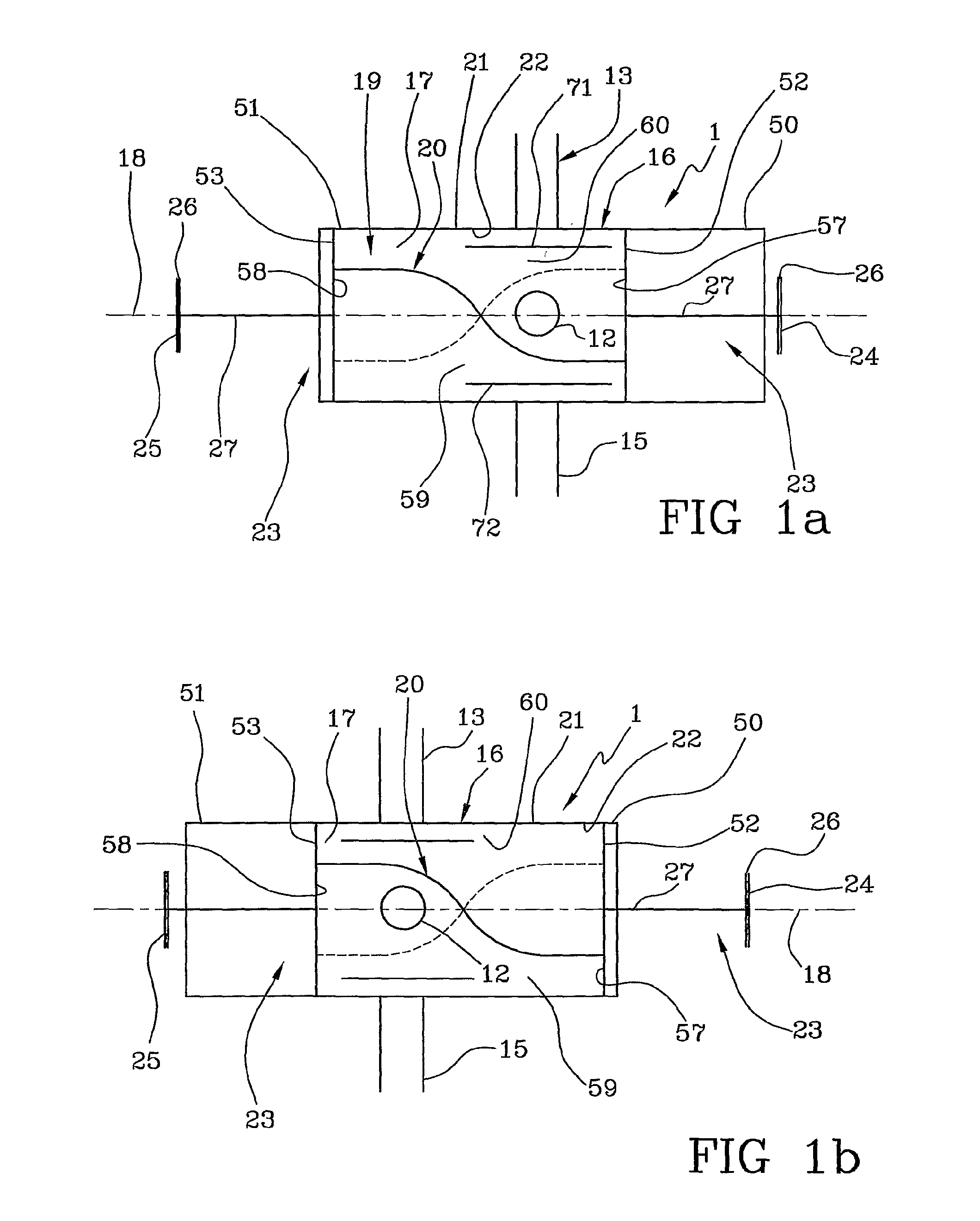
first and second embodiments (figs.1a , 1b , 2-5 , 9-10)
First and Second Embodiments (FIGS. 1A, 1B, 2-5, 9-10)
[0062]The device 1 presents a housing 16 having at least four ports: a first port 12, connected or connectable by means of a connector piece with portion 4a of line 4, a second port 13, connected or connectable by means of a connector piece with portion 4b of line 4, a third port 14, connected or connectable by means of a connector piece with portion 5a of line 5, and a fourth port 15, connected or connectable by means of a connector piece with portion 5b of line 5. The housing 16 has an internal chamber 17 presenting a longitudinal axis 18, a selector body 19 having at least an active portion 20 movable relative to the housing inside the internal chamber. More in detail the selector body is movable between at least a first position and a second position; in the first position of the selector body, the active portion is positioned relative to the housing so that the first port 12 is in fluid communication with the second port 13 ...
third embodiment
[0073]The device 1 of the third embodiment presents a housing 16 having four ports: a first port 12, connected or connectable by means of a connector piece with portion 4a of line 4, a second port 13, connected or connectable by means of a connector piece with portion 4b of line 4, a third port 14, connected or connectable by means of a connector piece with portion 5a of line 5, and a fourth port 15, connected or connectable by means of a connector piece with portion 5b of line 5. The housing 16 has an internal chamber 17 presenting a longitudinal axis 18, a selector body 19 having at least an active portion 20a, 20b movable relative to the housing inside the internal chamber. More in detail the selector body is movable between at least a first position and a second position; in the first position (FIGS. 12, 14 and 17) of the selector body, the active portion is positioned relative to the housing so that the first port 12 is in fluid communication with the second port 13 through sai...
PUM
 Abstract
Description
Claims
Application Information
 - R&D
- Intellectual Property
- Life Sciences
- Materials
- Tech Scout
- Unparalleled Data Quality
- Higher Quality Content
- 60% Fewer Hallucinations
Browse by: Latest US Patents, China's latest patents, Technical Efficacy Thesaurus, Application Domain, Technology Topic, Popular Technical Reports.
© 2025 PatSnap. All rights reserved.Legal|Privacy policy|Modern Slavery Act Transparency Statement|Sitemap|About US| Contact US: help@patsnap.com


