Expansion cone assembly for setting a liner hanger in a wellbore casing

a technology of expansion cone and wellbore, which is applied in the direction of borehole/well accessories, fluid removal, tubing catchers, etc., can solve the problems of reducing the inner diameter of the liner hanger and unable to retrieve the expansion cone through the previously set liner hanger

Active Publication Date: 2013-10-22
HALLIBURTON ENERGY SERVICES INC
View PDF10 Cites 4 Cited by
  • Summary
  • Abstract
  • Description
  • Claims
  • Application Information

AI Technical Summary

Benefits of technology

[0009]The present invention disclosed herein is directed to an expansion cone assembly for setting a liner hanger in a subterranean wellbore having a casing string previously installed therein. The expansion cone assembly of the present invention utilizes a dual cone configuration including a collapsible cone that is operable to plastically deform the liner hanger into sealing and gripping engagement with the casing string. In addition, expansion cone assembly of the present invention is operable to be retrieved through the liner hanger even after resilience in the casing string or the liner hanger reduces the inner diameter of the liner hanger after setting.
[0013]In another aspect, the present invention is directed to a method for setting a liner hanger. The method includes operably associating a setting tool having an expansion cone assembly with a liner string including the liner hanger, lowering the setting tool and the liner string into a wellbore casing, applying a force in the downhole direction to the expansion cone assembly such that a lead cone and a collapsible cone of the expansion cone assembly radially expand at least a portion of the liner hanger into contact with the wellbore casing, the collapsible cone having a first maximum diameter that is larger than a maximum outer diameter of the lead cone, decoupling the setting tool from the liner string, applying a force in the uphole direction to the expansion cone assembly and axially shifting the lead cone and the collapsible cone relative to an outer frustoconical surface of a cone mandrel such that the collapsible cone has a second maximum outer diameter that is no more than the maximum outer diameter of the lead cone.

Problems solved by technology

It has been found, however, that once the expansion cone has passed through and plastically deformed the liner hanger, resilience in the casing string and the liner hanger may result in a reduction in the inner diameter of the liner hanger.
When such inner diameter reduction occurs, retrieval of the expansion cone back through the previously set liner hanger may be difficult.

Method used


Image

  • Expansion cone assembly for setting a liner hanger in a wellbore casing
  • Expansion cone assembly for setting a liner hanger in a wellbore casing
  • Expansion cone assembly for setting a liner hanger in a wellbore casing

Examples


Embodiment Construction

[0023]While the making and using of various embodiments of the present invention are discussed in detail below, it should be appreciated that the present invention provides many applicable inventive concepts, which can be embodied in a wide variety of specific contexts. The specific embodiments discussed herein are merely illustrative of specific ways to make and use the invention, and do not delimit the scope of the invention.

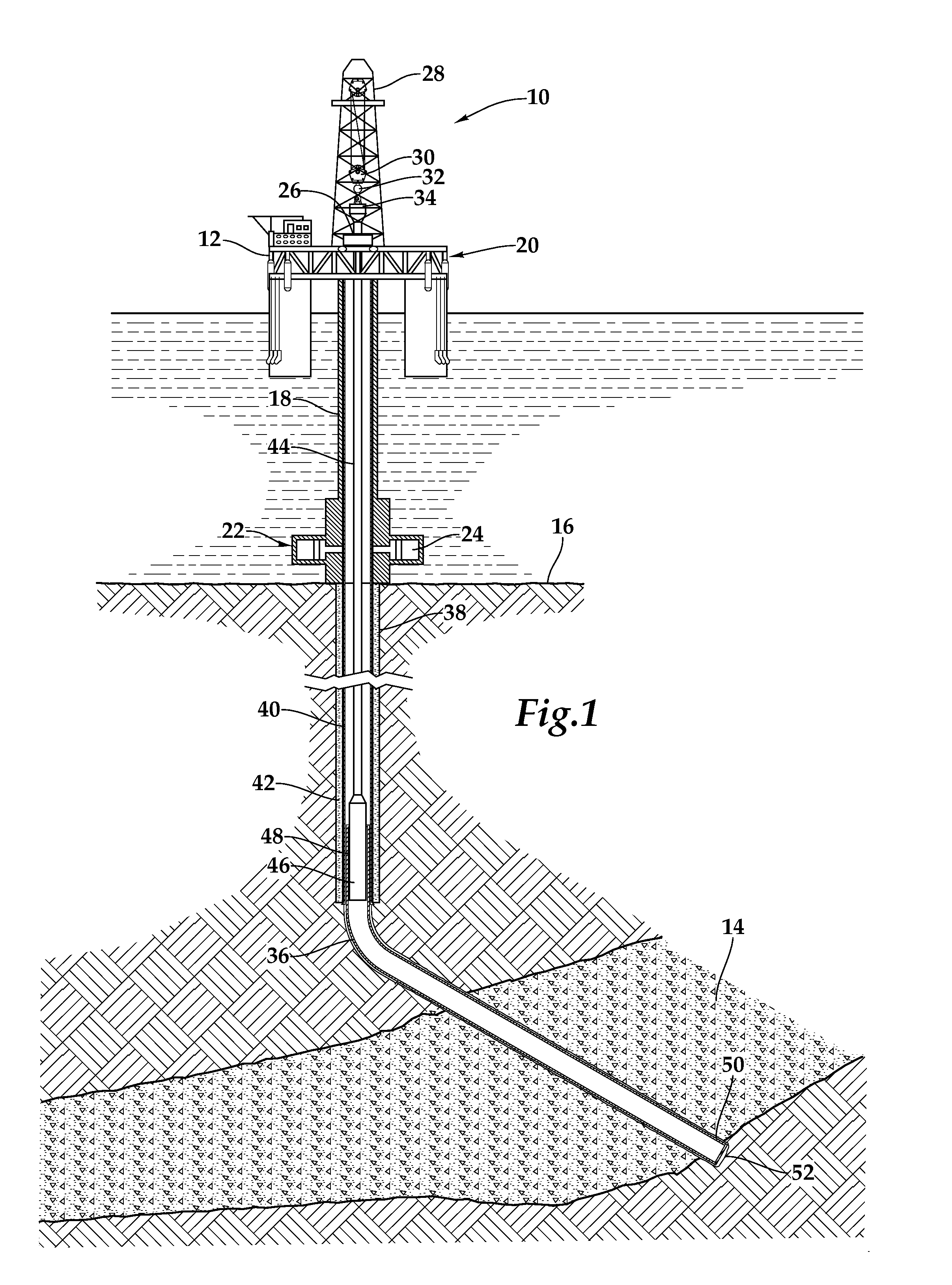
[0024]Referring initially to FIG. 1, an apparatus for installing a liner string in a casing string previously installed in a subterranean wellbore being deployed from an offshore oil or gas platform is schematically illustrated and generally designated 10. A semi-submersible platform 12 is centered over submerged oil and gas formation 14 located below sea floor 16. A subsea conduit 18 extends from deck of platform 12 to wellhead installation 22, including blowout preventers 24. Platform 12 has a hoisting apparatus 26, a derrick 28, a travel block 30, a hook 32...


PUM


Abstract

An expansion cone assembly (200) for setting a liner hanger. The expansion cone assembly (200) includes a cone mandrel (202) having an outer frustoconical surface (220), a lead cone (206) slidably disposed around the cone mandrel (200) having a frustoconical surface (228) with a maximum outer diameter (230) and a collapsible cone (204) slidably disposed at least partially around the outer frustoconical surface (220) of the cone mandrel (202). In an expansion configuration, the outer frustoconical surface (220) radially props the collapsible cone (204) such that it has a first maximum outer diameter (232) that is greater than the maximum outer diameter (230) of the lead cone (206). In a retrieval configuration, the collapsible cone (204) axially shifts relative to the outer frustoconical surface (220) such that it has a second maximum outer diameter (234) that is no more than the maximum outer diameter (230) of the lead cone (206).

Description

FIELD OF THE INVENTION[0001]This invention relates, in general, to equipment utilized in conjunction with operations performed in subterranean wells and, in particular, to an expansion cone assembly for setting a liner hanger in a subterranean wellbore having a casing string previously installed therein.BACKGROUND OF THE INVENTION[0002]Without limiting the scope of the present invention, its background is described with reference to constructing a subterranean well, as an example.[0003]In conventional practice, the drilling of an oil or gas well involves creating a wellbore that traverses numerous subterranean formations. For a variety reasons, each of the formations through which the well passes is preferably isolated. For example, it is important to avoid an undesired passage of formation fluids into the wellbore and an undesired passage of wellbore fluids into a formation. In addition, it is important to prevent fluids from producing formations to enter or contaminate non produci...

Claims


Application Information

Patent Timeline
Patent Type & Authority Patents(United States)
IPC IPC(8): E21B23/00
CPCE21B43/105E21B33/04
Inventor HAZELIP, GARY LYNN
Owner HALLIBURTON ENERGY SERVICES INC
Why Eureka
Try Eureka