
Photo-voltaic power generation equipment that can automatically track the sun

a technology of photovoltaic power generation and sun, applied in the direction of light radiation electric generators, heat collector mounting/support, lighting and heating apparatus, etc., can solve the problems of no domestic 2-axis tracking system has been verified by works, electronic elements are subject to very easy damage, and the adjustment degree of freedom is increased, and the effect of improving the absorption and utilization rate of sunligh

Inactive Publication Date: 2013-09-24
ET ENERGY
View PDF13 Cites 2 Cited by
  • Summary
  • Abstract
  • Description
  • Claims
  • Application Information

AI Technical Summary

Benefits of technology

[0005]To improve adjustment by existing automatic sun-tracking device, which can only adjust tilting angle of photo-voltaic assembly in a limited range, so that direct (perpendicular) incidence of sunlight on solar cell platform cannot be ensured all the time, this utility model provides a type of photo-voltaic power generation equipment that can automatically track the sun with higher degrees of freedom of adjustment.
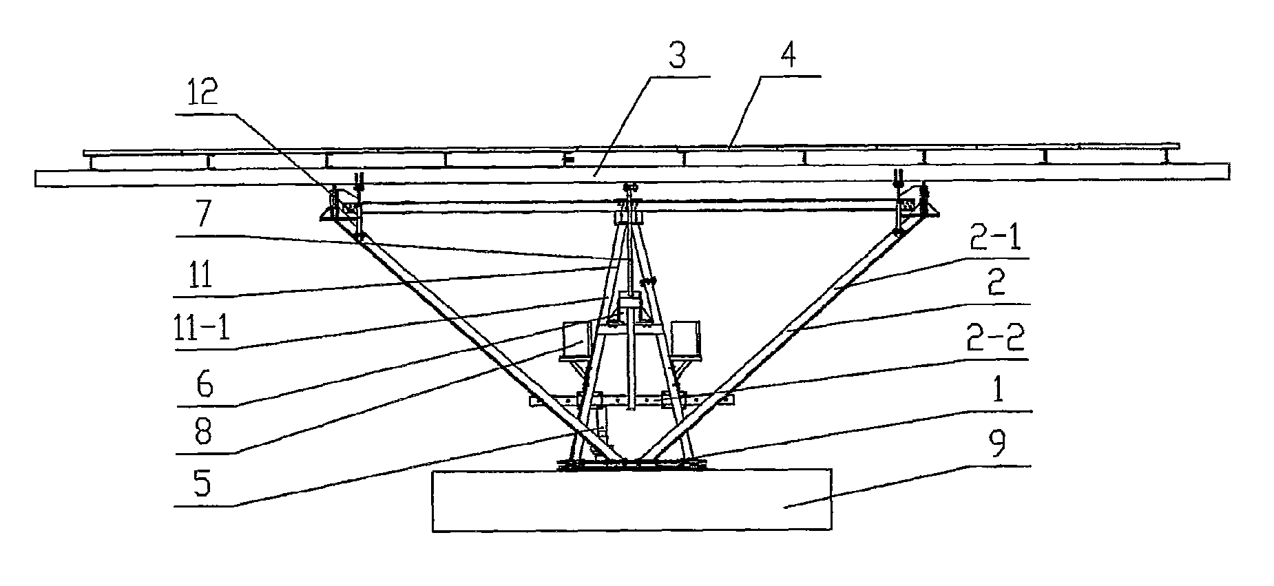
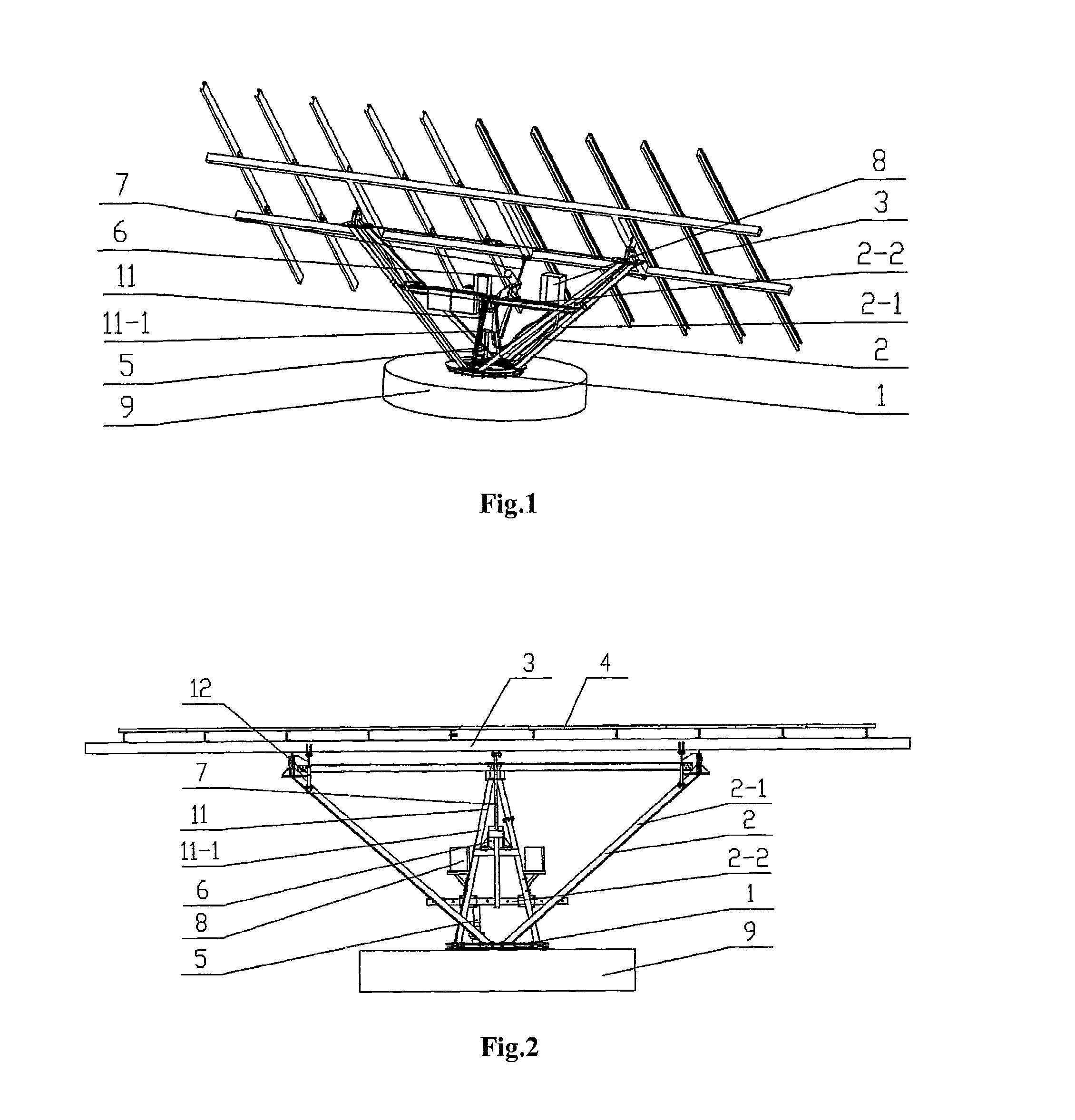
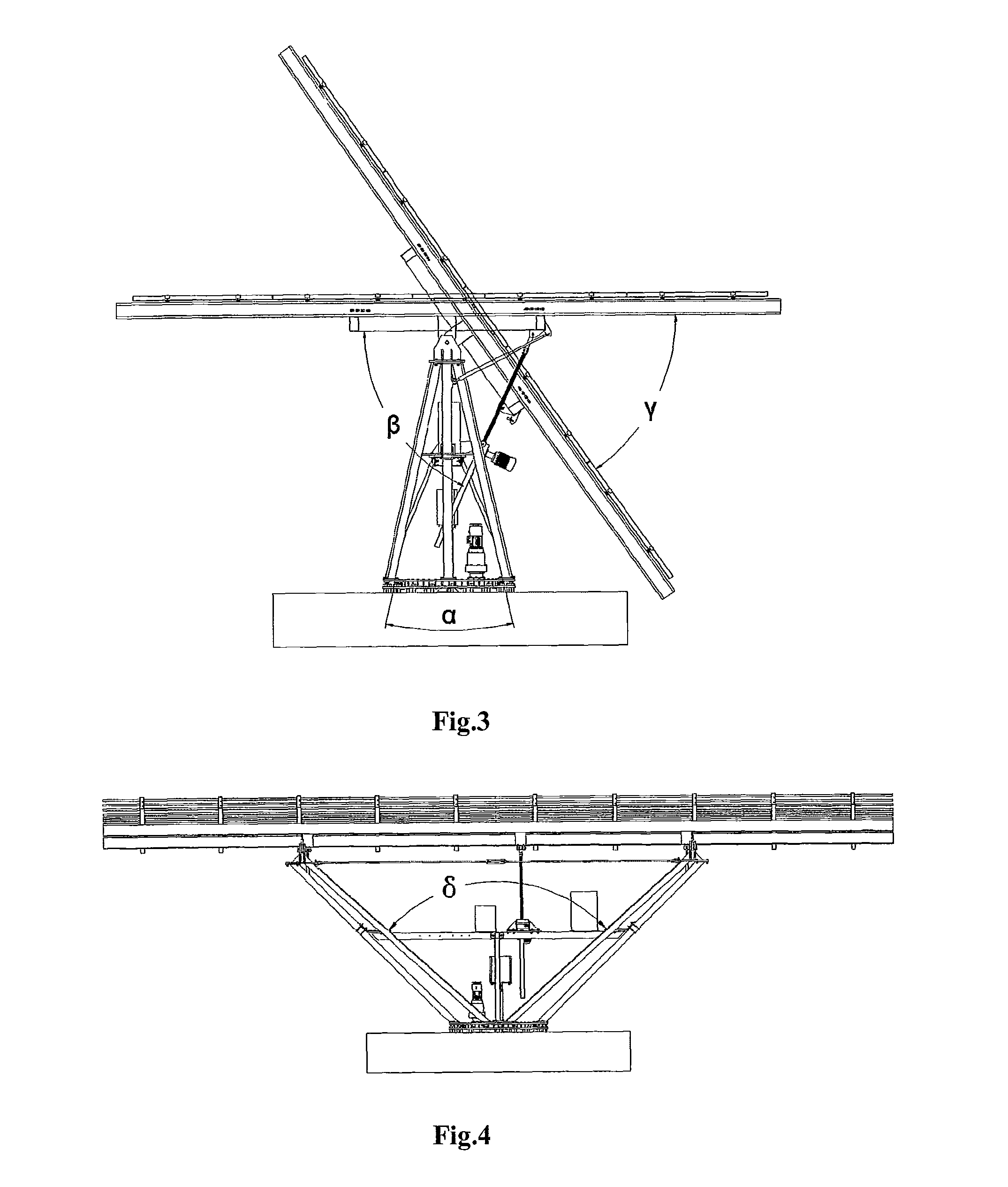
[0006]In one embodiment, the present invention is directed to the following: A type of photo-voltaic power generation equipment that can automatically track the sun, comprising pedestal installed on mounting platform, main support frame installed on pedestal, solar cell panel platform installed on main support frame, and solar energy photo-voltaic assembly installed on solar cell panel platform, said pedestal is connected to and rotates relative to mounting platform, and pedestal circumferentially driven planet reduction gear is installed on pedestal; said main support frame includes left and right main support arms, the upper ends of which are hinged to solar cell panel platform and the lower ends of which are fixed on pedestal, forming a “V” type structure of angle δ in 110°·130°; between left and right main support arms is a cross beam, on which platform elevation angle adjustment lifter is fixed; end of telescopic link of lifter is hinged to solar cell panel platform, hinge points of main support arms are right above pedestal, and these hinges points are not on the same straight line with the hinge point of telescopic link; said pedestal circumferentially driven planet reduction gear and platform elevation angle adjustment lifter are connected to electric control device. In this way, based on sole pitch adjustment, circumferential adjustment of solar energy photo-voltaic assembly is realized, so that degrees of freedom of track of sun are increase and sunlight will always be incident on the assembly perpendicularly, increasing solar energy absorption and utilization rate.
[0008]To further enhance load bearing capacity of main support frame, said main support arms include at least 2 left arms and 2 right arms installed and fixed symmetrically. Besides, said main support arms at each side are installed in the shape of “^” (angle α is 17°·25°), upper ends of main support arms are combined and hinged to solar cell panel platform, and their lower ends are fixed on outer circumference of pedestal.
[0009]To further enhance load bearing capacity of support, at middle part of said main support frame, an auxiliary support frame is provided and consists of 4 auxiliary support arms; upper ends of said auxiliary support arms are combined and hinged to solar cell panel platform, these hinged points are on the same straight line with hinged points of main support arms, and lower ends of auxiliary support arms are fixed on pedestal; cross beam is installed and fixed at one side of auxiliary support arms.
[0010]To avoid sharp turn of solar cell panel platform during adjustment resulting in equipment damage, buffering air spring is further provided at hinge between main support arm and solar cell panel platform.
[0012]This utility model realizes circumferential and pitching adjustment of photo-voltaic power generation equipment, increases adjustment degrees of freedom for automatic tracking of the sun, and improves absorption and utilization rate of sunlight. Besides, this equipment features high structural strength, can withstand very large dynamic load and adapt to complicated and severe outdoor operation environment, and has very strong resistance against wind. Grade 12 hurricane and max. wind speed of 135 km / h can be withstood. On photo-voltaic assembly mounting plane, most photo-voltaic assemblies currently manufactured can be installed. Also, it is not necessary to bury the pedestal underground, allowing easy manufacture, assembling, installation, and maintenance, and high performance-price ratio of complete set system.

Problems solved by technology

A photo-voltaic system synchronized with a grid is becoming a hot point of research worldwide whether independent or synchronized with grid, how to make use of limited space and area, and increase efficiency of a photo-voltaic power generation system, so as to gain maximum energy, has become an important issue.
At present, domestic scientific workers and enterprises have developed some tracking devices, but only in laboratories, mainly due to small increase of efficiency by use of tracking system as compared with costs of tracking device, or low reliability, complicated structure, large power and high energy consumption of tracking motor, or complicated circuits (their electronic elements are subject to very easy damage in severe outdoor environment during winter and summer) of such devices designed.
Up to now, no domestic 2-axis tracking system has been verified by works of scale, and in particular, medium and large size 2-axis tracking systems that can be used for synchronized photo-voltaic power generation are absent.

Method used


Image

  • Photo-voltaic power generation equipment that can automatically track the sun
  • Photo-voltaic power generation equipment that can automatically track the sun
  • Photo-voltaic power generation equipment that can automatically track the sun

Examples


Embodiment Construction

[0020]FIG. 1 shows a type of photo-voltaic power generation equipment that can automatically track the sun. This equipment features pedestal 1 installed on mounting platform 9. On said pedestal 1, embedded parts can be provided for fixing and connection with mounting platform 9. On pedestal 1, main support frame 2 is provided, on which solar cell panel platform 3 is installed. On platform 3, solar energy photo-voltaic assembly 4 is provided. Said main support frame 2 comprises left and right main support arms 2-1 (in the shape of a fork). Upper ends of main support arms 2-1 are hinged to solar cell panel platform 3, and their lower ends are fixed on pedestal 1. The whole support is in the shape of a “V” of angle δ in 110°·130°, as shown in FIG. 4. At each side, 3 main support arms 2-1 are provided, ensuring sufficient structural strength. At each side, main support arms 2-1 are installed in the shape of “^” and angle α between outmost two main support arms 2-1 is 17°·25°, as shown i...


PUM


Abstract

This invention relates to a type of solar energy photo-voltaic power generation equipment that can automatically track the sun. This device includes a pedestal installed on a mounting platform. On the pedestal, a main support frame is provided. On the support frame, a solar cell panel platform is provided. On this platform, a solar energy photo-voltaic assembly is installed. The pedestal is connected to the mounting platform and can rotate relative to the mounting platform. On the pedestal, a circumferentially driven planet reduction gear is installed. On the main support frame, a platform elevation angle adjustment lifter is installed. The end of the telescopic link on the lifter is hinged to the solar cell panel platform. The circumferentially driven planet reduction gear and platform elevation angle adjustment lifter are connected to an electric control device.

Description

TECHNICAL FIELD[0001]This invention relates to a type of solar energy photo-voltaic power generation equipment that can automatically track the sun, which belongs to solar energy application technical field.BACKGROUND OF THE INVENTIONRelated Art[0002]With development of solar energy photo-voltaic power generation, solar energy photo-voltaic power generation systems of independent operation and synchronized with a grid are playing an important role in power supply for remote places where other power supplies are not available and in mitigating of short power supply in cities respectively. A photo-voltaic system synchronized with a grid is becoming a hot point of research worldwide whether independent or synchronized with grid, how to make use of limited space and area, and increase efficiency of a photo-voltaic power generation system, so as to gain maximum energy, has become an important issue. If automatic tracking device can be used for solar energy collection equipment, so that s...

Claims


Application Information

Patent Timeline
Patent Type & Authority Patents(United States)
IPC IPC(8): H02N6/00H01L31/042F24S50/20
CPCF24J2/542H01L31/042F24J2/5233F24J2002/5292F24J2002/5462Y02E10/47Y02E10/50F24S25/13F24S30/452F24S2025/02F24S2030/134H02S20/32
Inventor WANG, XINGHUA
Owner ET ENERGY
Learn More