
Thermal plate precipitation measurement system

a precipitation measurement and thermoplastic plate technology, applied in the field of meteorological instruments, can solve the problems of system b>20/b> not being able to accurately determine if the precipitation is rain or snow, and still suffering from noise generation

Active Publication Date: 2013-08-13
BOARD OF RGT NEVADA SYST OF HIGHER EDUCATION ON BEHALF OF THE DESERT RES INST +1
View PDF11 Cites 1 Cited by
  • Summary
  • Abstract
  • Description
  • Claims
  • Application Information

AI Technical Summary

Benefits of technology

The invention provides a thermal plate precipitation measurement system that includes two thermal plates, each at a different temperature. The system can measure the rate of precipitation by comparing signals received from the two thermal plates at both temperatures. The system is easy to operate and can provide accurate results even when measuring small amounts of precipitation. The technical effect of the invention is to provide a more reliable and efficient method for measuring precipitation rates.

Problems solved by technology

A problem experienced with these types of systems is that the overall accuracy of the system is dependent upon the mechanical resolutions of accumulation.
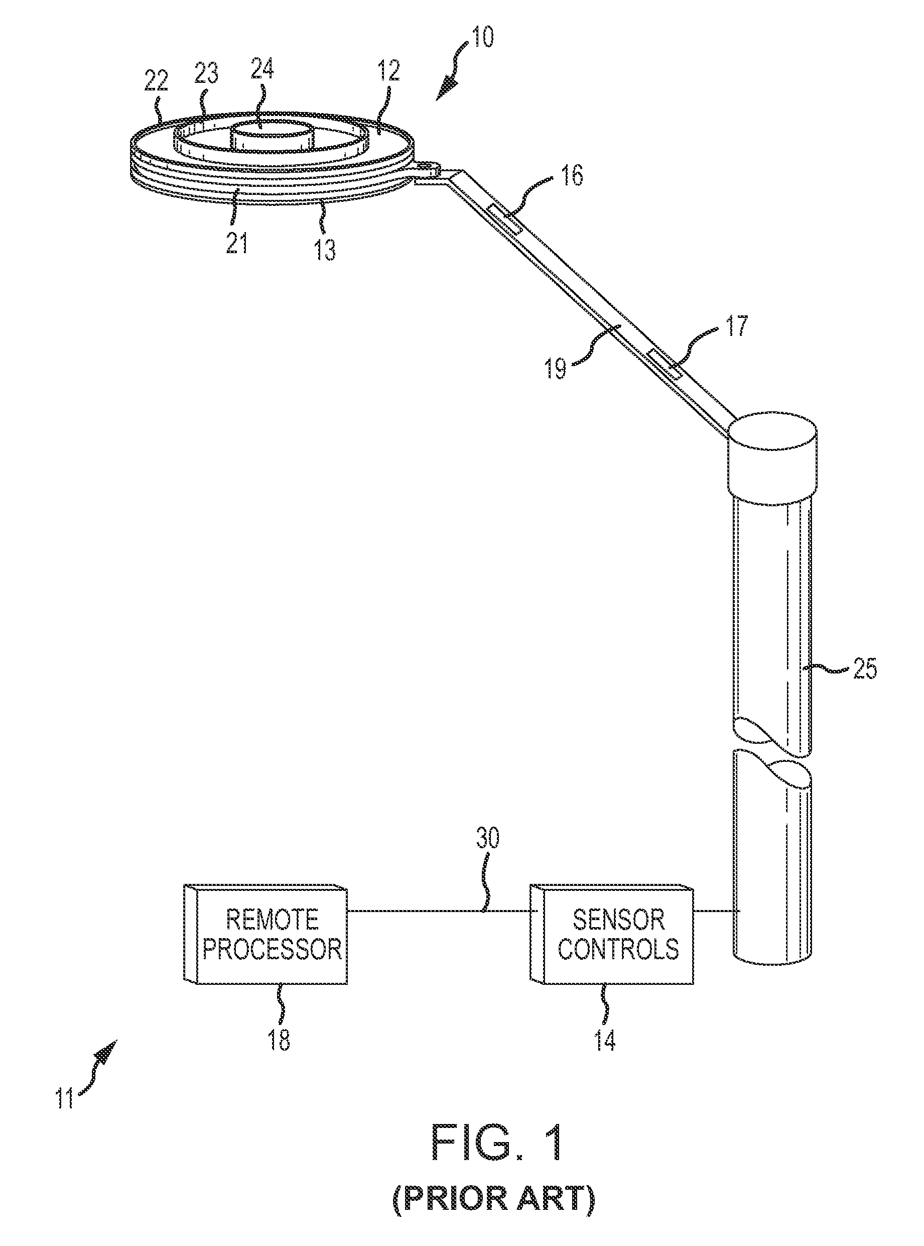
Further, the measurement system 20 is unable to adequately determine if the precipitation is rain or snow.
While the thermal plate systems described above improve upon the mechanical measurement systems, they still suffer from noise generated from short and long wave radiation, sustained updrafts / downdrafts over the plate, non-horizontal orientation of the thermal plates, etc.
Further, the thermal plate systems currently available have difficulty properly determining what type of precipitation is present.

Method used


Image

  • Thermal plate precipitation measurement system
  • Thermal plate precipitation measurement system
  • Thermal plate precipitation measurement system

Examples


Embodiment Construction

[0024]FIGS. 3-6 and the following description depict specific examples to teach those skilled in the art how to make and use the best mode of the invention. For the purpose of teaching inventive principles, some conventional aspects have been simplified or omitted. Those skilled in the art will appreciate variations from these examples that fall within the scope of the invention. Those skilled in the art will appreciate that the features described below can be combined in various ways to form multiple variations of the invention. As a result, the invention is not limited to the specific examples described below, but only by the claims and their equivalents.

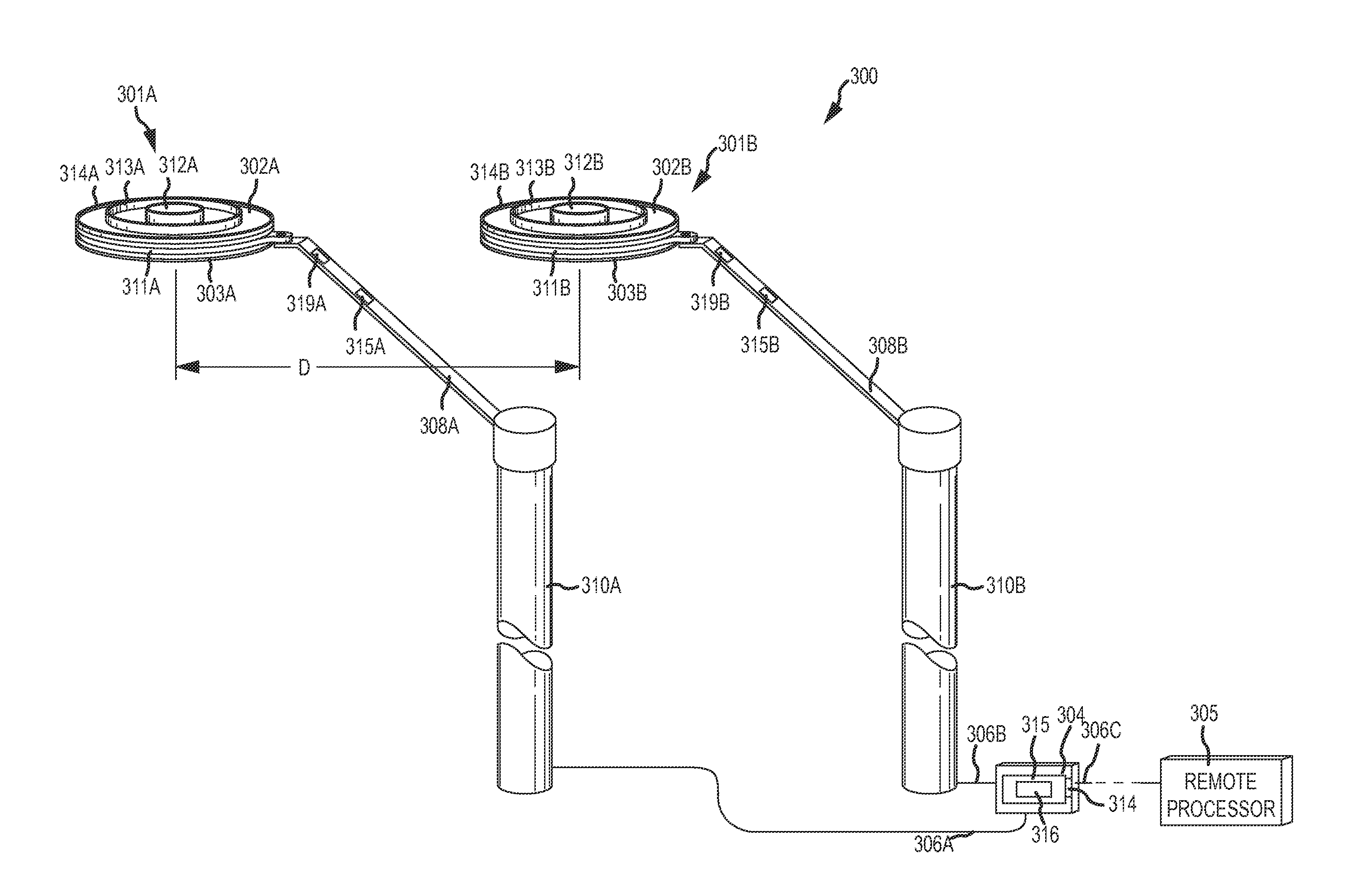
[0025]FIG. 3 shows a thermal plate precipitation measurement system 300 according to an embodiment of the invention. According to an embodiment of the invention, the thermal plate precipitation measurement system 300 comprises a first thermal plate system 301A and at least a second thermal plate system 301B. The thermal plate syst...


PUM


Abstract

A thermal plate precipitation measurement system (300) and a method of operating the thermal plate precipitation measurement system (300) is provided. The thermal plate precipitation measurement system (300) includes a first thermal plate system (301A) with first and second thermal plates (302A, 303A) and a second thermal plate system (301B) with first and second thermal plates (302B, 303B). A precipitation rate can be determined by configuring the first and second thermal plates (302A, 303A) of the first thermal plate system (301A) at a first temperature and configuring the first and second thermal plates (302B, 303B) of the second thermal plate system (301B) at a second temperature different than the first temperature. A differential power consumption between the first and second thermal plates (302A, 303A, 302B, 303B) of each of the first and second thermal plate systems (301A, 301B) can be determined and the precipitation rate can be determined based on a difference between the differential power consumption of the first thermal plate system (301A) and the differential power consumption of the second thermal plate system (301B).

Description

GOVERNMENT LICENSE RIGHTS[0001]This invention was made with Government support under DTFAWA-03-C-00049 awarded by the Federal Aviation Administration. The Government has certain rights in this invention.TECHNICAL FIELD[0002]The present invention relates to meteorological instrumentation, and more particularly, to an improved method and apparatus for detection and quantification of precipitation that reaches the earth's surface at a specific location.BACKGROUND OF THE INVENTION[0003]There are numerous prior art precipitation measurement systems available. As used in the present application, precipitation includes, but is not limited to, rain, mist, drizzle, fog, snow, freezing rain, freezing drizzle, sleet, and hail. Currently, there are various rain gauges and snow gauges known that are designed to quantify precipitation that reaches the earth's surface. Some prior art systems attempt to quantify the precipitation based on a measurable weight of precipitation that accumulates in a c...

Claims


Application Information

Patent Timeline
Patent Type & Authority Patents(United States)
IPC IPC(8): G01W1/00
CPCG01W1/14
Inventor RASMUSSEN, ROYHALLET, JOHN
Owner BOARD OF RGT NEVADA SYST OF HIGHER EDUCATION ON BEHALF OF THE DESERT RES INST
Learn More