
Bicycle with suspension

a technology of suspension and bicycle, which is applied in the direction of shock absorbers, foldable cycles, cycle equipment, etc., can solve the problems of increased labor, increased cost, and increased cost, and achieves the effect of reducing the number of adjustments and reducing the number of times of us

Active Publication Date: 2013-07-09
SPECIALIZED BICYCLE COMPONENTS INC
View PDF34 Cites 77 Cited by
  • Summary
  • Abstract
  • Description
  • Claims
  • Application Information

AI Technical Summary

Benefits of technology

The patent describes a method and assembly for adjusting the sag position of a bicycle's suspension. The method involves inflating the gas chamber of the shock absorber to a high pressure, compressing the shock absorber by a person, and deflating the gas chamber while the person is on the bike. The assembly includes a shock absorber with a gas chamber, a movable piston, and at least one valve for inflating and deflating the gas chamber. The gas chamber can be divided by the piston into two changeable volumes, and the valve can be positioned to communicate with either volume. The technical effects of the patent include improved suspension performance and adjustability of sag position for different rider preferences.

Problems solved by technology

However, because mountain bikes are typically pedal-driven, i.e., use the rider's power output to propel the bicycle, the provision of rear suspension, especially, may undesirably absorb a rider's power output, resulting in wasted effort.
Accordingly, rear suspension systems commonly incorporated on engine-driven vehicles, such as motorcycles, have proven undesirable for use with pedal-driven vehicles, such as mountain bikes.
Rear suspension systems of engine-driven vehicles commonly emphasize strength over weight and, therefore, have not been widely incorporated on mountain bikes.
All of these different adjustments can be overwhelming to a user, especially a less experienced rider.
Not only do some shock absorbers have multiple adjustments but some adjustments require a specific procedure that can be time consuming and difficult to perform.
This can further complicate the procedure.
Because of the perceived difficultly of certain, if not all of the adjustments, some riders may have the shock absorber adjusted or set-up when it is originally purchased and then make no further adjustments.
In addition, certain bike shops or consumers may not make all of the right adjustments.

Method used


Image

  • Bicycle with suspension
  • Bicycle with suspension
  • Bicycle with suspension

Examples


Embodiment Construction

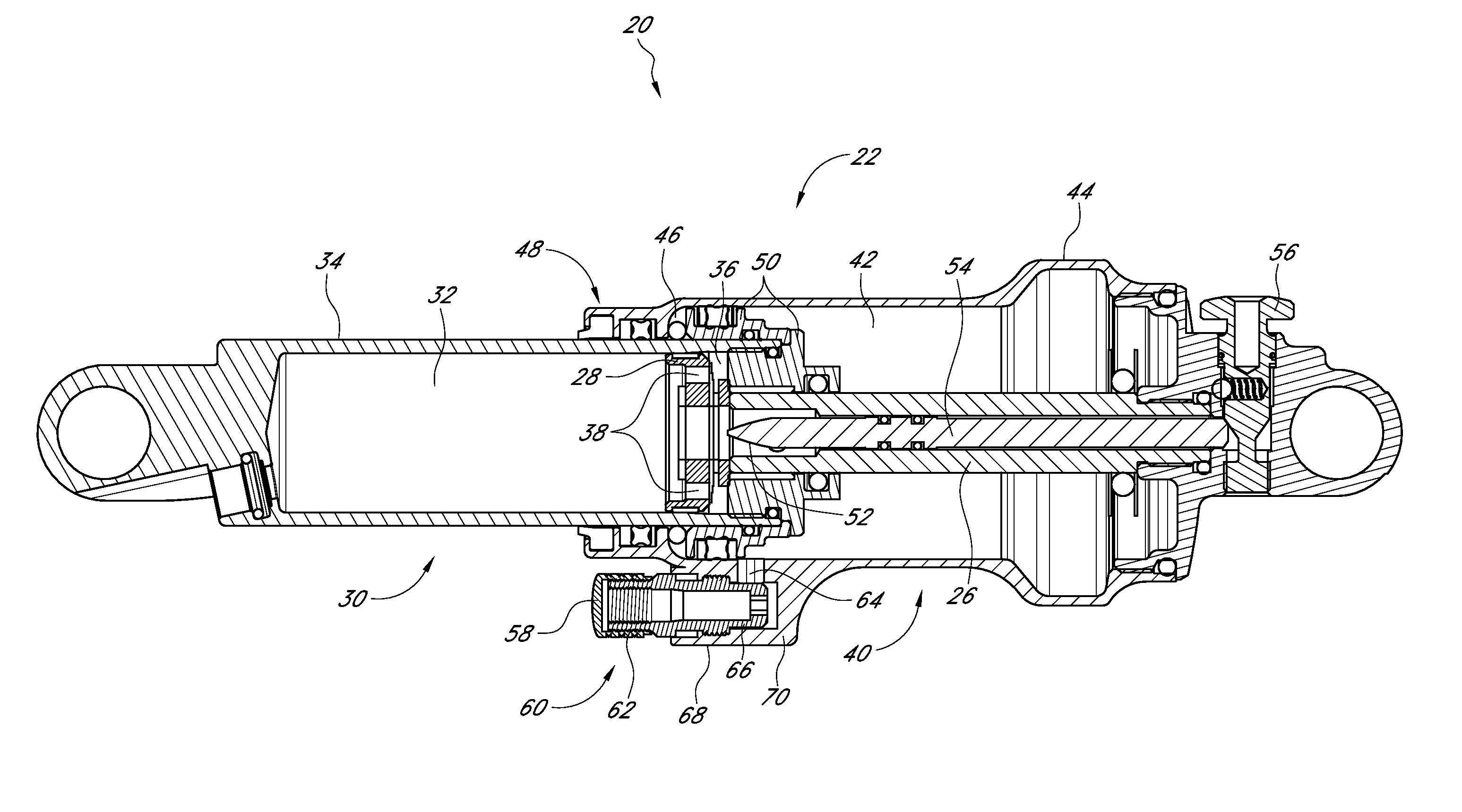
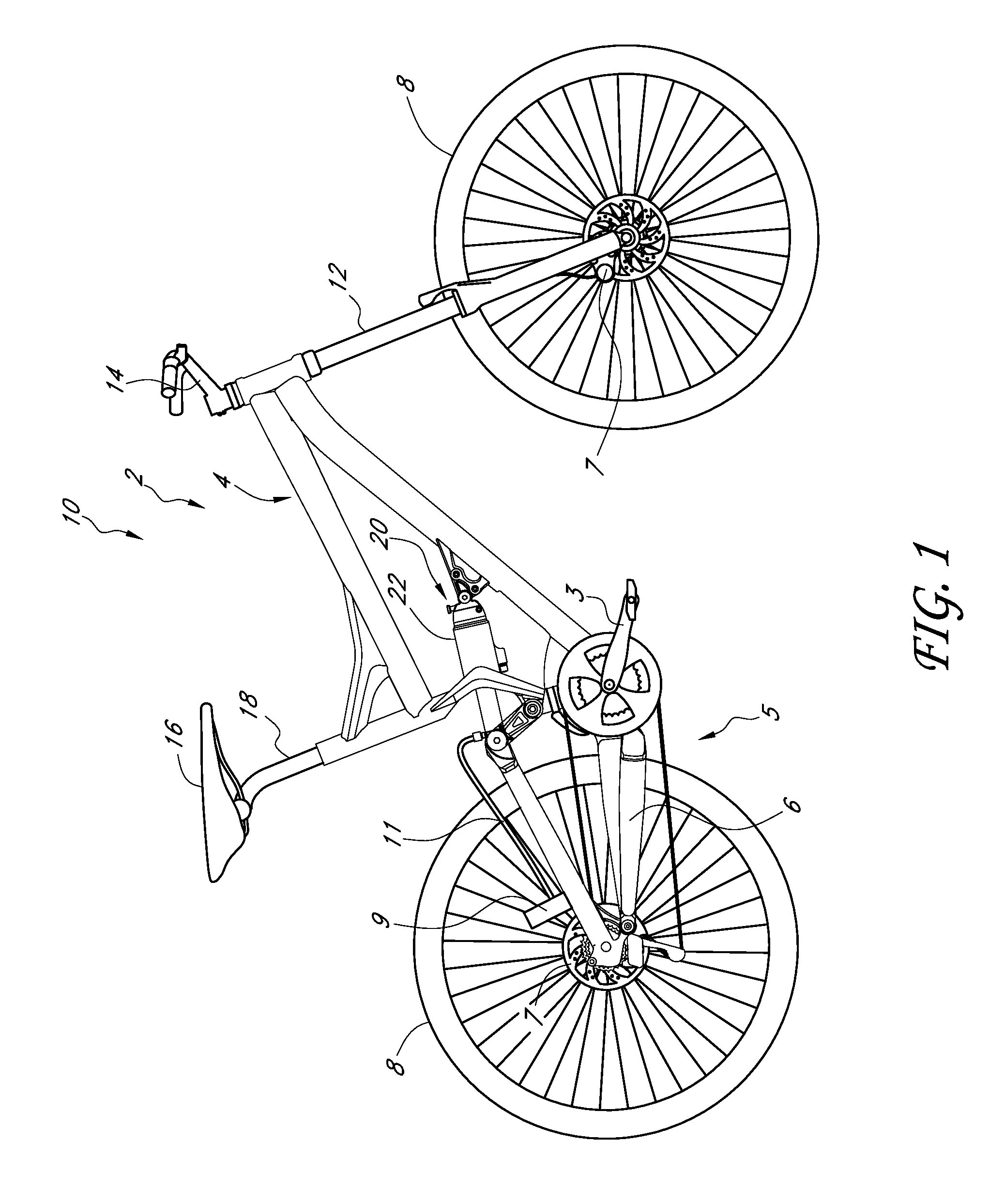
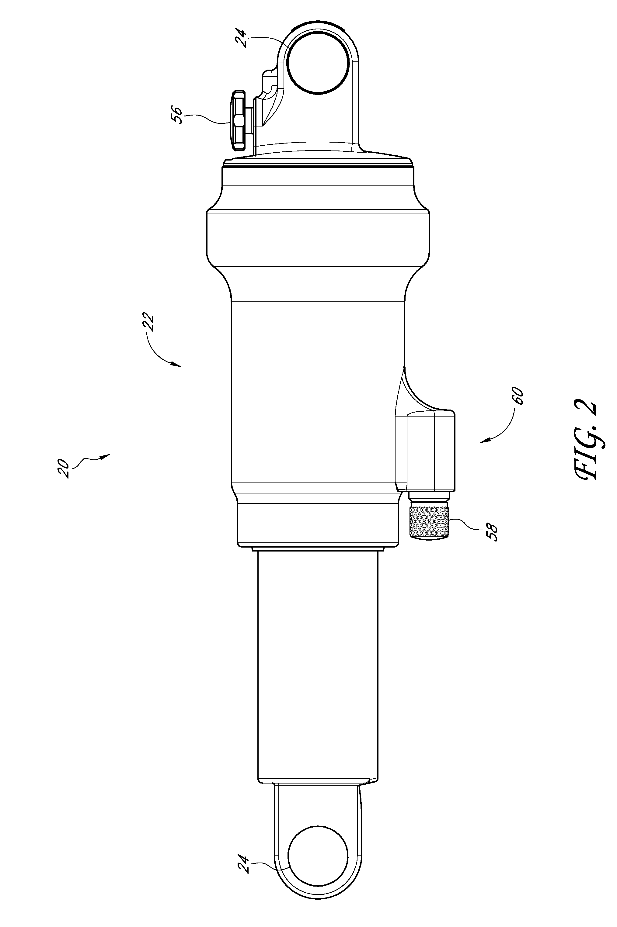
[0033]FIG. 1 illustrates an off-road bicycle, or mountain bike 10, including a preferred embodiment of a rear suspension assembly, or shock absorber. The bicycle 10 is described herein with reference to a coordinate system wherein a longitudinal axis extends from a forward end to a rearward end of the bicycle 10. A vertical, central plane generally bisects the bicycle 10 and contains the longitudinal axis. A lateral axis extends normal to the longitudinal axis and lies within a horizontal plane. In addition, relative heights are generally expressed as elevations relative to a horizontal surface on which the bicycle 10 is supported in an upright position. The above-described coordinate system is provided for the convenience of describing the bicycle illustrated in FIG. 1, and is non-limiting. In addition, certain features and components of the bicycle may be described in terms of relative positions or directions within the particular positions and orientations reflected in the drawin...


PUM


Abstract

A bicycle can include a suspension system with a shock absorber. The shock absorber can have a sag position which can be adjustable. Sag refers to the amount of movement experienced by the suspension under a static load, such as that of the weight of a rider. Methods and systems to set sag can include at least one valve in fluid communication with a gas chamber of the shock absorber. In some embodiments, the at least one valve can be used to automatically set the sag position based on an individual's weight and riding position.

Description

CROSS-REFERENCE TO RELATED APPLICATIONS[0001]N / ABACKGROUND OF THE INVENTION[0002]1. Field of the Invention[0003]The present invention relates generally to bicycle suspension systems. In particular, the present invention relates to shock absorbers and suspension assemblies suitable for use in connection with off-road bicycles.[0004]2. Description of the Related Art[0005]Off-road bicycles, or mountain bikes, may be equipped with front and rear suspension assemblies operably positioned between the frame of the bicycle and the front and rear wheels, respectively. Providing front and rear suspension on a mountain bike potentially improves handling and performance by absorbing bumps, and other rough trail conditions, which may be encountered while riding off-road. However, because mountain bikes are typically pedal-driven, i.e., use the rider's power output to propel the bicycle, the provision of rear suspension, especially, may undesirably absorb a rider's power output, resulting in wast...

Claims


Application Information

Patent Timeline
Patent Type & Authority Patents(United States)
IPC IPC(8): B60G15/12
CPCB62K25/20F16F9/56F16F9/06B62K25/04B62K25/286F16F9/062F16F9/3271
Inventor TALAVASEK, JAN
Owner SPECIALIZED BICYCLE COMPONENTS INC
Learn More