
Animation stand with multiple axis camera support

a technology of multiple axis and camera support, which is applied in the direction of projectors, camera body details, instruments, etc., can solve the problems of safety hazards, two devices consume excessive space, and it takes longer to set up equipmen

Active Publication Date: 2013-06-25
JOHN LEMMON FILMS
View PDF25 Cites 13 Cited by
  • Summary
  • Abstract
  • Description
  • Claims
  • Application Information

AI Technical Summary

Benefits of technology

The patent describes an animation stand that can hold a camera, lighting, and backdrops to create hand-made two-dimensional and stop-motion animation. The stand can be adjusted for different camera angles and positions. This allows for easier and more flexible animation production.

Problems solved by technology

The fact that one device is used to create two dimensional animation and a different device is used to create stop-motion animation results in these disadvantages:1) The animator must spend extra time learning how to operate two devices instead of one.2) The two devices consume excessive space.3) It takes longer to set up the equipment.
The design involves heating glass which could result in a safety hazard.
U.S. Pat. No. 3,415,600 to Yarbrough (1968) describes another device that has limited functionality because it is usable only for two dimensional animation.
Also, the complexity of the design necessitates that the animator spend a substantial amount of time learning how to operate the apparatus.
The following designs have the disadvantages of being useable for two dimensional animation only, and of being designed in a way that does not allow portability, ease of storage and ease of use: U.S. Pat. No. 1,805,511 to Carpenter (1931), U.S. Pat. No. 2,153,902 to Tondreau (1939), and U.S. Pat. Nos. 2,198,006 and 2,281,033, both to Garity (1940, 1942).
The disadvantages of these designs are:1) They can only be used for creating stop-motion animation and not for two dimensional animation.2) After moving the object, the animator must move aside while the camera procures the still image; otherwise the animator will be in the shot.3) Computer cables and power cords must extend along the floor for several feet to reach camera, computer and lights, which creates a safety hazard for the animator.4) When these designs are used in a classroom setting it is likely that students will trip on tripod legs or power cords, which can ruin an animated scene and could cause injury.

Method used


Image

  • Animation stand with multiple axis camera support
  • Animation stand with multiple axis camera support
  • Animation stand with multiple axis camera support

Examples


first embodiment

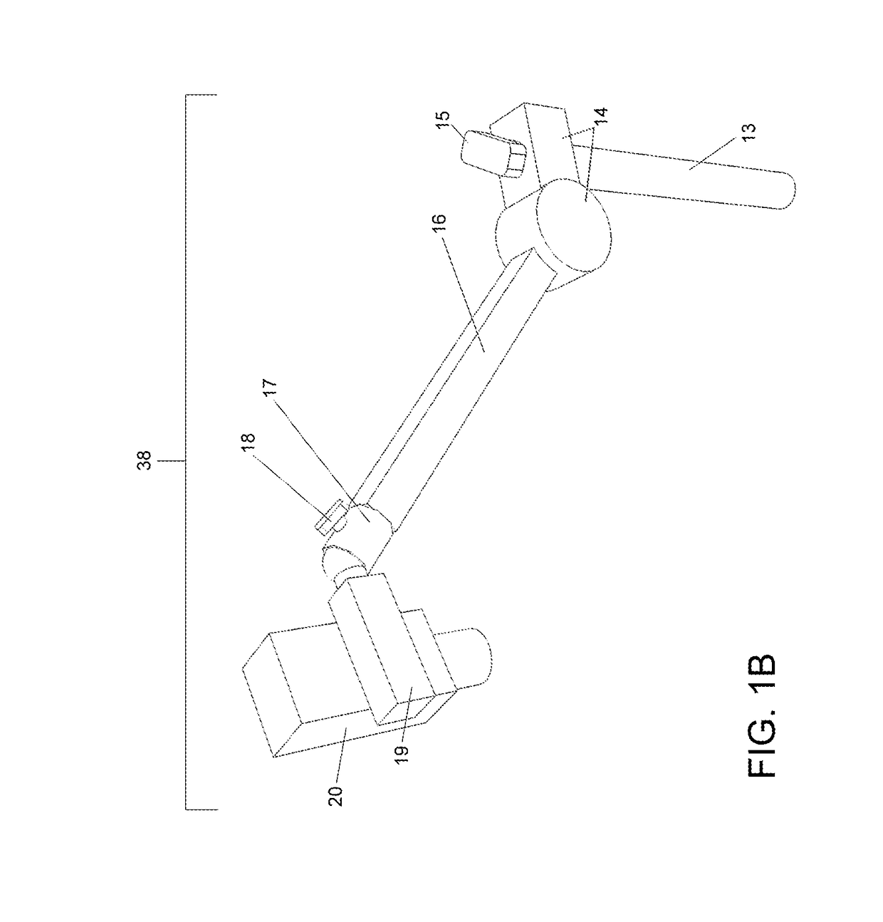
[0058]The animation stand is operated by an animator who sits or stands facing the front edge of base 10 (the edge nearest registration pegs 11). To create two-dimensional animation, the animator positions camera support assembly 38 so that the camera is aimed down toward base 10 and stage panel 12 (FIG. 1A).

[0059]The animator adjusts camera support assembly 38 using the following steps. First, turn knob 15 counterclockwise to loosen it, then rotate rotary hinge 14 around the vertical axis of vertical arm 13 so that camera 20 is centered above stage panel 12, then tighten knob 15 to lock said camera. Second, use rotary hinge 14 to adjust the angle of the horizontal arm 16 so that camera 20 is the desired height above stage panel 12. Third, turn knob 18 counterclockwise to loosen articulating joint 17 around camera support arm 19, allowing said camera support arm to be rotated through all axes (X, Y and Z) around the point where said camera support arm intersects with said articulati...


PUM


Abstract

An animation stand which provides a camera support assembly that enables a camera to be positioned along any axis which allows users to create traditional, hand-made animation, specifically two-dimensional animation using a variety of art techniques and stop-motion animation of poseable figures and everyday objects.

Description

CROSS-REFERENCED TO RELATED APPLICATIONS[0001]Not ApplicableFEDERALLY SPONSORED RESEARCH[0002]Not ApplicableSEQUENCE LISTING OR PROGRAM[0003]Not ApplicableBACKGROUND OF THE INVENTION[0004]1. Field of Invention[0005]This invention relates to animation stands, specifically to animation stands which provide adjustable support for camera, lighting and backdrops for use in creating traditional, hand-made animation.[0006]2. Prior Art[0007]Traditional, or hand-made, animation is normally created in one of two ways: 1) Two dimensional animation involves creating a series of hand-drawn images. This type of animation is referred to as ‘cel animation’ or ‘cartoon animation’. Images are procured by placing the drawings on a planar surface. Above that surface is a camera, connected to a horizontal support which is attached to a vertical column, which is attached to the planar surface (or base). This device is referred to as an ‘animation stand’. 2) Stop-motion animation is created by moving phys...

Claims


Application Information

Patent Timeline
IPC IPC(8): G03B21/14
CPCG03B15/06G03B17/561
Inventor LEMMON, JOHN POWELLROSINSKI, MICHAEL SCOTT
Owner JOHN LEMMON FILMS
Learn More