
Compact eyepiece using an imersed field lens

a compact, field-to-field technology, applied in the field of head mounted display systems, can solve the problems of insufficient normal distortion equation using the tangent, and no combination of examples allows for the correction of distortion on a flat plane using spherical surfaces

Active Publication Date: 2013-06-04
EMAGIN CORP +1
View PDF6 Cites 4 Cited by
  • Summary
  • Abstract
  • Description
  • Claims
  • Application Information

AI Technical Summary

Benefits of technology

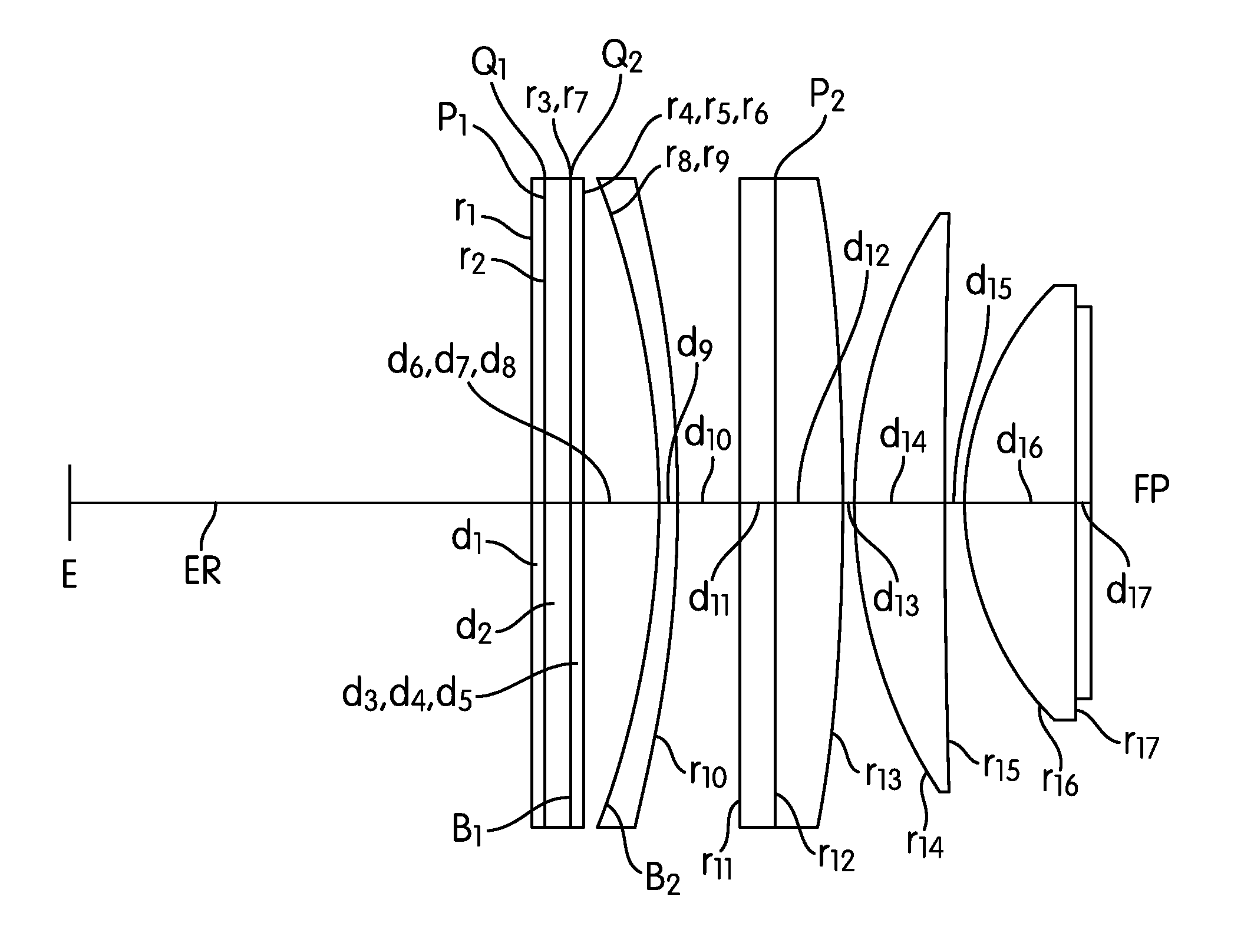
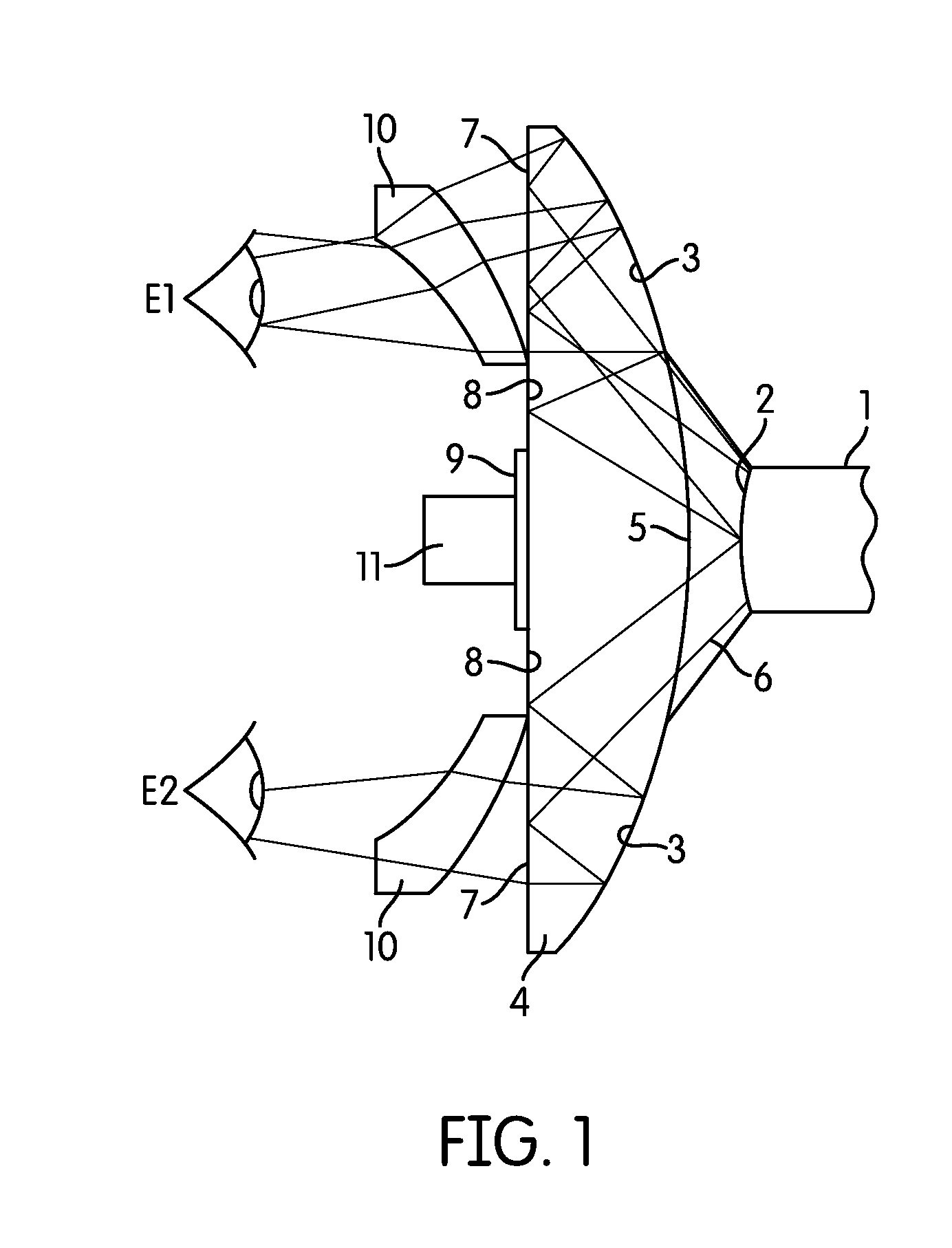
The patent describes two different lens systems that use a series of spherical elements to create a wide field of view with no distortion. These systems have at least one concave reflecting surface and three convex refracting surfaces with opposite radii. The second embodiment also includes a negative lens substrate. These lens systems work by using a mapping that matches the height and effective focal length of the optic, which ensures that the system produces an image without distortion. The lens systems are designed to match the mapping used by most image generators and cameras. In each embodiment, a field lens is always immersed in contact with the image source. Overall, the invention provides a wide field of view with optical correction over a wide field of view without distortion.

Problems solved by technology

Because these systems can have fields of view larger than 180°, the normal distortion equation using the tangent is inadequate.
However, no combination of the examples allows for the correction of distortion on a flat plane using spherical surfaces.

Method used


Image

  • Compact eyepiece using an imersed field lens
  • Compact eyepiece using an imersed field lens
  • Compact eyepiece using an imersed field lens

Examples


example 2

[0047 is similar to Example 1 however the system departs from zeroing the third order coefficients in favor of balancing the third order aberrations with higher order aberrations. This system benefits from a concave reflector substrate with a high index of refraction and a numerically low dispersion. The mirror substrate can then be used to color correct the system.

[0048]Example 3 illustrates how the color correction can be moved to other lenses in the system. In this example the substrate of the concave reflector has a low index of refraction and a numerically high dispersion. The general shape of the elements remains the same with one of the convex refractive radii being drawn from the left while the following two convex refracting radii drawn from the right. A slightly better color correction and slightly better monochromatic correction can be achieved by achromatizing the individual elements. The design can also slightly improve by changing the curvature of r1. When used with sm...


PUM


Abstract

A first embodiment is a lens system having a plurality of refractive and reflective spherical elements that work as a magnifier to produce a distortion free, less than 1%, image with optical correction over a wide field of view. The system has at least one concave reflecting surface, and at least three convex refracting surfaces with the sign of the radius of one of the convex refracting surfaces being opposite of the sign of the radius of remaining two convex refracting surfaces. A second embodiment is a lens having a concave reflecting element which is on a substrate that is a negative lens by transmission with an index of refraction between 1.6<nd >2.0 and a dispersion 49<νd>15. This is used in combination with at least 3 positive refracting surfaces with less dispersive power than the negative element and with the sign of the radius of one of the positive elements being opposite from the sign of the radius of the remaining positive elements.

Description

CROSS REFERENCE TO RELATED APPLICATIONS[0001]This application is related to U.S. Ser. No. 61 / 334,052 filed on May 12, 2010 entitled “Compact Eyepiece Using an Immersed Field Lens” by Paul Weissman and hereby incorporated herein by reference.FIELD OF INVENTION[0002]The present invention generally relates to head mounted display systems for viewing electronically generated images that are projected as a virtual image and more particularly relates to using a compact eyepiece with an immersed field lens.BACKGROUND[0003]There is a general need for eyepieces and viewing devices. A sector of these viewing devices finds their way into the field of head-borne (helmet-mounted) displays. When used as head borne displays an important consideration is size and weight. Reduction of the size and weight are at a premium and often other requirements are relaxed. Relaxed requirements can be optical performance at the edge of the field or distortion. However it is desirable to have low weight and smal...

Claims


Application Information

Patent Timeline
Patent Type & Authority Patents(United States)
IPC IPC(8): G02B27/14G02B17/00
CPCG02B25/001
Inventor WEISSMAN, PAUL
Owner EMAGIN CORP
Learn More