
Connector

a technology of electrical connectors and connectors, applied in the direction of coupling device connections, coupling device details, engagement/disengagement of coupling parts, etc., can solve the problems of difficult to achieve perfect alignment between the connectors just before establishing the connection, and certain degree of misalignment, etc., to achieve less precise handling of the housing parts

Inactive Publication Date: 2013-05-07
NOKIA TECH OY
View PDF15 Cites 3 Cited by
  • Summary
  • Abstract
  • Description
  • Claims
  • Application Information

AI Technical Summary

Benefits of technology

[0020]It is another object of the present invention to provide method of assembling a housing for a moveable connector that requires a less precise handling of the housing parts.

Problems solved by technology

Perfect alignment between the connectors just before establishing the connection is very difficult to achieve and a certain degree of misalignment has to be accepted.
Known floating connectors often have only one direction of movement and / or are not self centering and / or have a complicated construction.

Method used


Image

  • Connector
  • Connector
  • Connector

Examples


Embodiment Construction

[0029]In the following detailed description, the connector according to the invention will be described by the preferred embodiments.

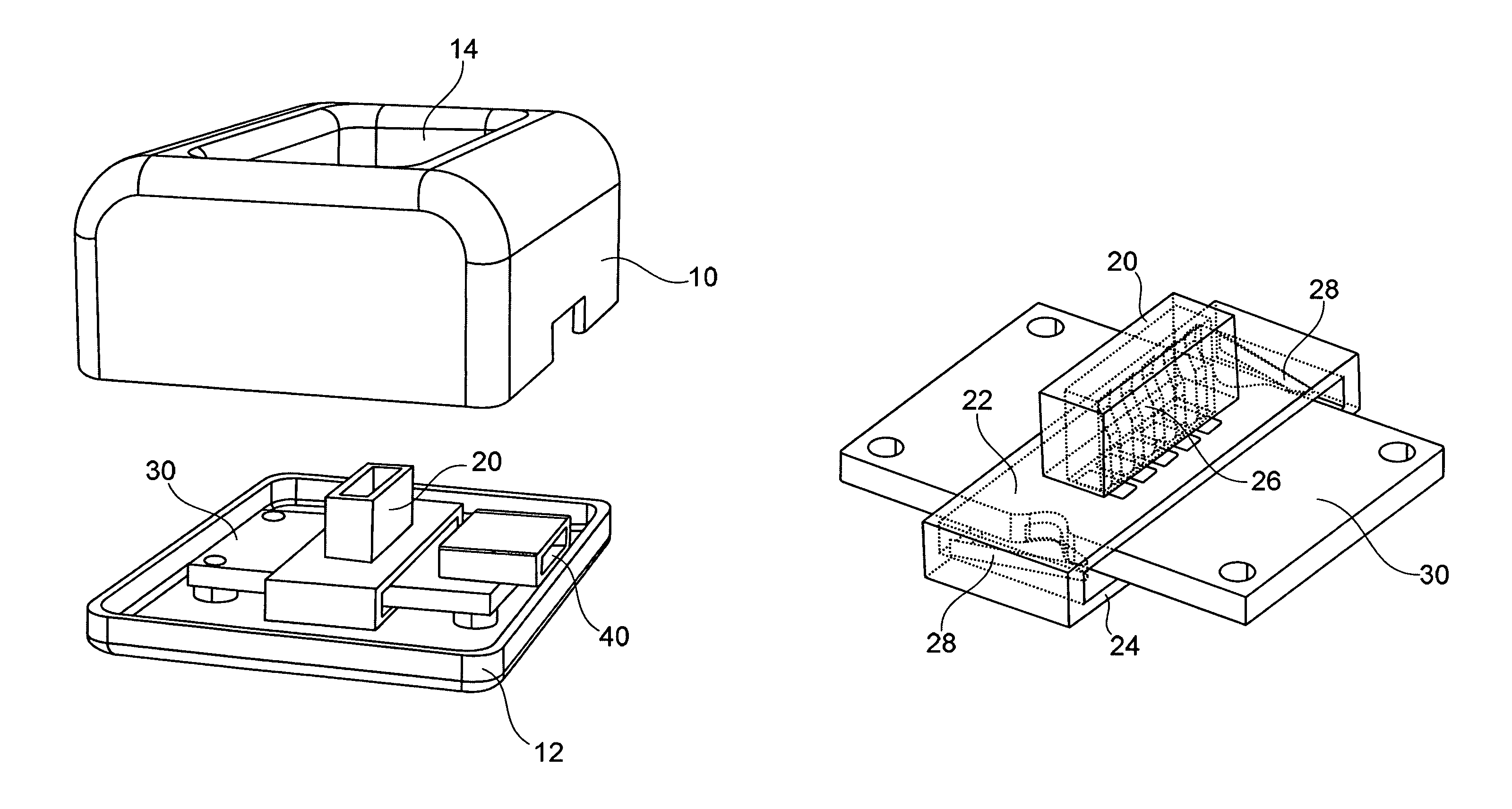
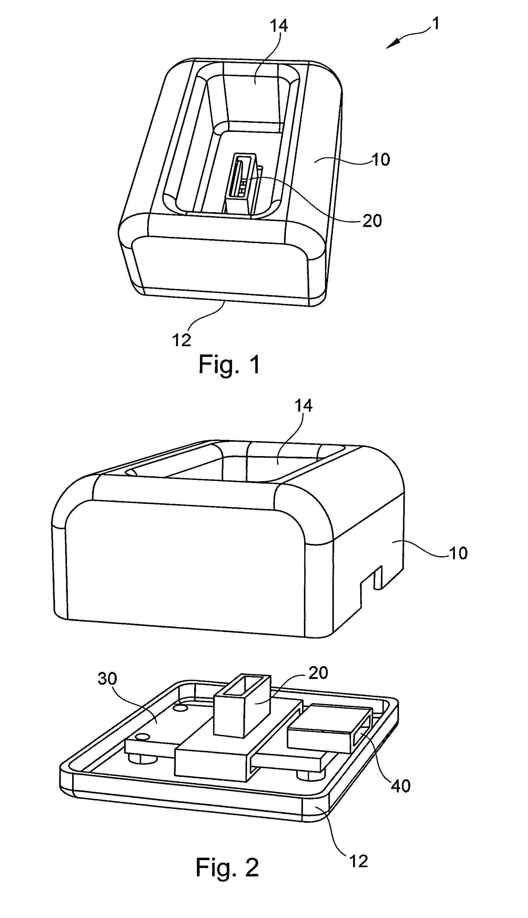
[0030]With reference to FIG. 1 the movable / floating connector according to an embodiment of the invention is included in a cradle or desk stand 1. The cradle 1 includes a housing 10 that includes a base 12 the housing 10 defines a bay 14. The bay 14 is designed for receiving a portion of a peripheral device, such as a mobile phone, a personal navigation assistant, a music or multimedia player, a camera, a palmtop computer other portable or mobile electronic device for creating an electrical connection therewith and for supporting the peripheral device.

[0031]An electrical connector assembly 20 is placed at the bottom of the bay 10.

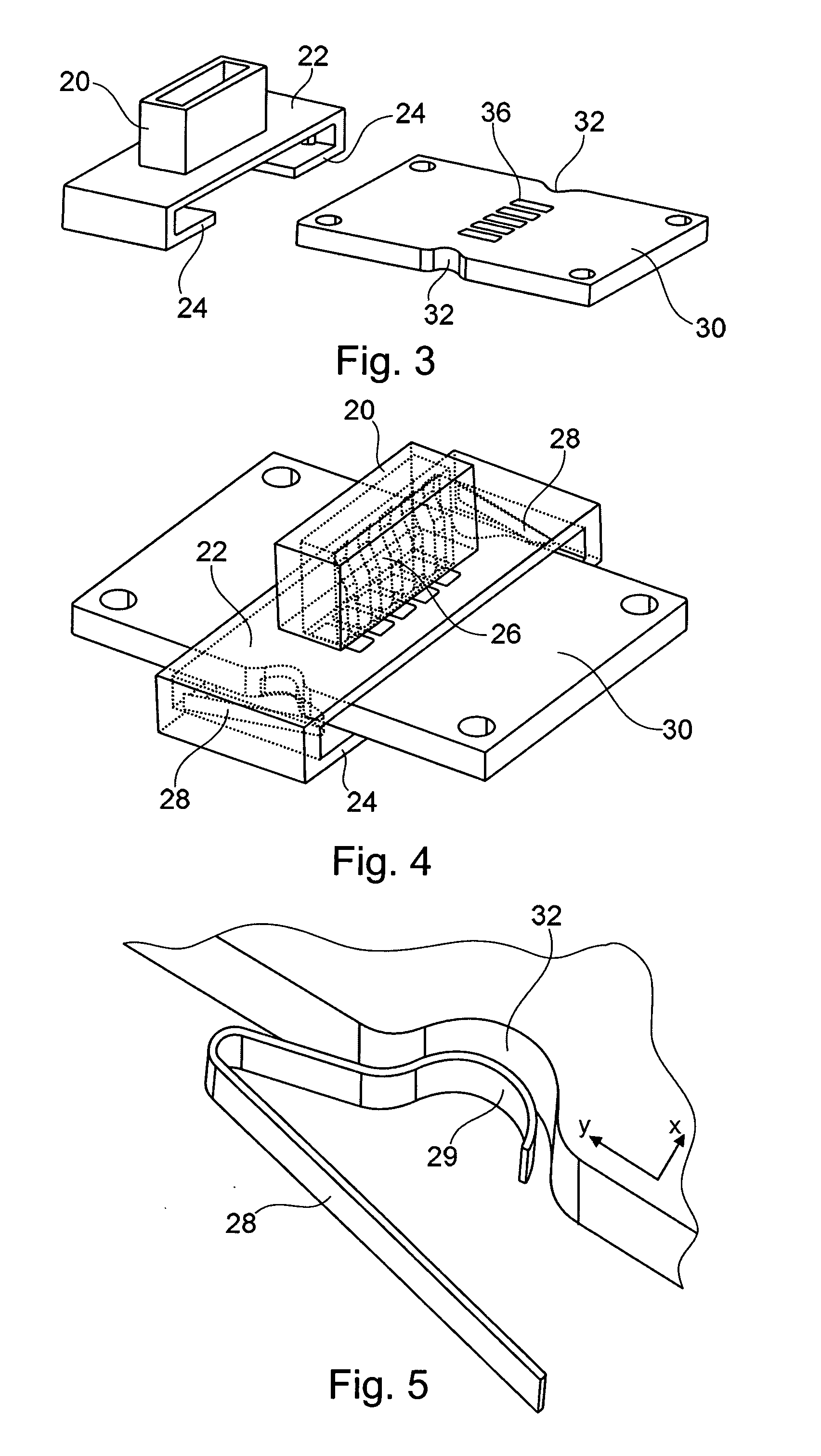
[0032]With reference to FIG. 2 the electrical connector assembly 20 is suspended from a printed wired board 30. Another connector assembly 40 is attached to the printed wired board 30. The connector assembly 40 is fixed (not m...


PUM

PropertyMeasurementUnit
forceaaaaaaaaaa
resilientaaaaaaaaaa
flexibleaaaaaaaaaa

Abstract

A connector includes a connector assembly is supported by a moveable member that can move relative to a printed wired board in two directions and is urged to its center position by two oppositely disposed springs that each urge a contact member into a respective recess.

Description

RELATED APPLICATION[0001]This application was originally filed as PCT Application No. PCT / EP2007 / 005124 on Jun. 11, 2007, which is incorporated herein by reference in its entirety.FIELD OF THE INVENTION[0002]The present invention relates to electrical connectors for coupling electronic devices to another device, for example in desk stands or other cradles.BACKGROUND OF THE INVENTION[0003]Stroke type pairs e.g. between digital cameras and their desk stands are known in the art. Perfect alignment between the connectors just before establishing the connection is very difficult to achieve and a certain degree of misalignment has to be accepted. In known desk stand solutions these tolerances are handled with one or two floating printed wired boards and with one captive cable that is fixed / soldered permanently to the printed wired board inside the desk stand or inside the desk stand there is floating printed wired board and a separate flexible printed circuit connected to the external I / O...

Claims


Application Information

Patent Timeline
Patent Type & Authority Patents(United States)
IPC IPC(8): H01R12/00
CPCH01R13/6315Y10T29/49208H01R12/7005
Inventor FAHLLUND, JAN H.SILVENNOINEN, KAIKNUUTTILA, OSMO
Owner NOKIA TECH OY
Learn More